
Control system and CPU unit

a control system and cpu technology, applied in computing, instruments, electric digital data processing, etc., can solve the problems of increasing the production cost of the entire system, duplication of lines, and inability to sustain the availability of the control system in use, so as to improve availability and facilitate the location

Inactive Publication Date: 2011-06-02
HITACHI LTD
View PDF2 Cites 6 Cited by
  • Summary
  • Abstract
  • Description
  • Claims
  • Application Information

AI Technical Summary

Benefits of technology

[0007]The object of this invention, which has been made to solve the above mentioned problem, is to provide a communication apparatus and a control system used in it, which can enjoy an improved availability and also can locate the positions of abnormalities throughout the network lines.
[0022]In the control system, the loop of the line of 1st path and the loop of the line of 2nd path are formed connecting an active CPU unit and each of remote input / output units, the direction of data frame transfer through the loop of the line of 1st path being opposite to that of the data frame transfer through the loop of the line of 2nd path. By constructing the network of the control system in such a manner as described above, the network can exhibit a high resistivity to line failures that may concentrate on a single spot and therefore provide a high availability.
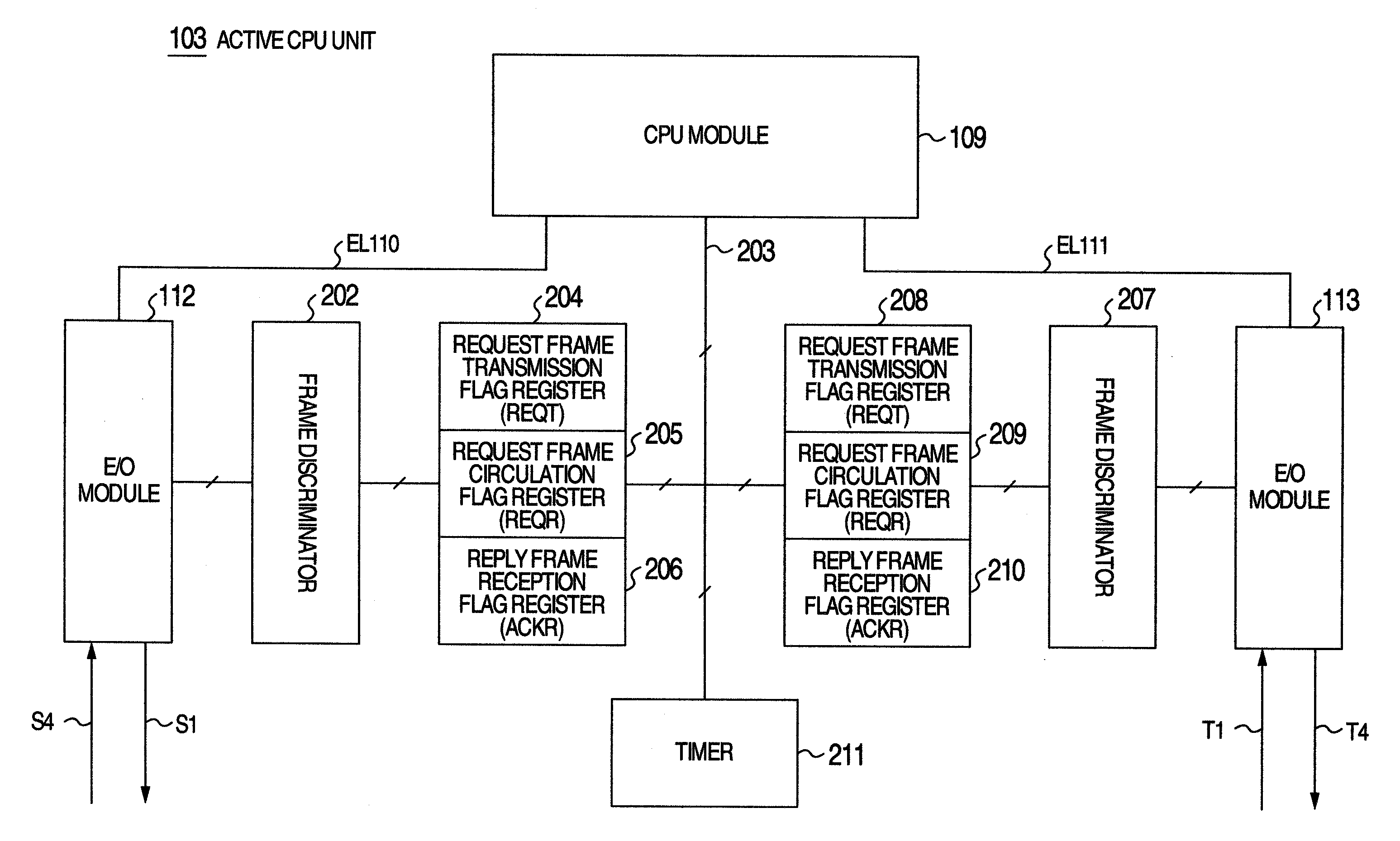
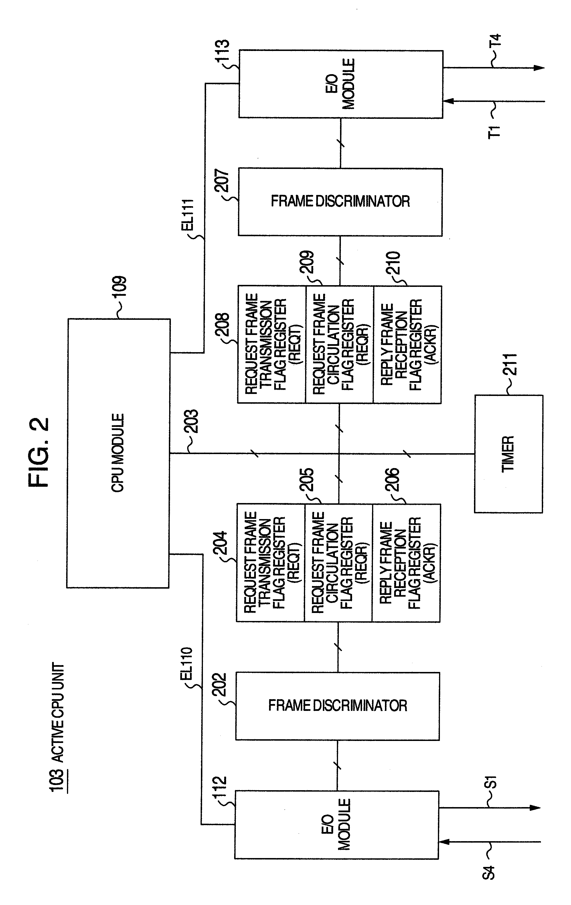
[0036]According to this CPU unit, it can be made easy to locate the positions of abnormalities in the ring-shaped network by checking the time-out in the ring-shaped network with the three flag registers.
[0037]According to this invention, a communication apparatus and a control system can be provided which can improve availability and locate the positions of abnormalities.

Problems solved by technology

Indeed, a single CPU is a load consuming low power, but if a plurality of RIO units are used, so many CPU units must accompany them.
Thus, the CPUs result in the increase in the production cost of the entire system.
However, it was ascertained that when a number of controlled systems appear on the network, the mere duplication of lines cannot sustain the availability of the control system in use.
For example, in a network where a number of RIO modules are connected linearly with a CPU unit, a break in an intermediate portion of the network line may cause the possibility of the RIO module at the extreme end failing in communication, to rise to the maximum level.

Method used


Image

  • Control system and CPU unit
  • Control system and CPU unit
  • Control system and CPU unit

Examples


Embodiment Construction

Entire System

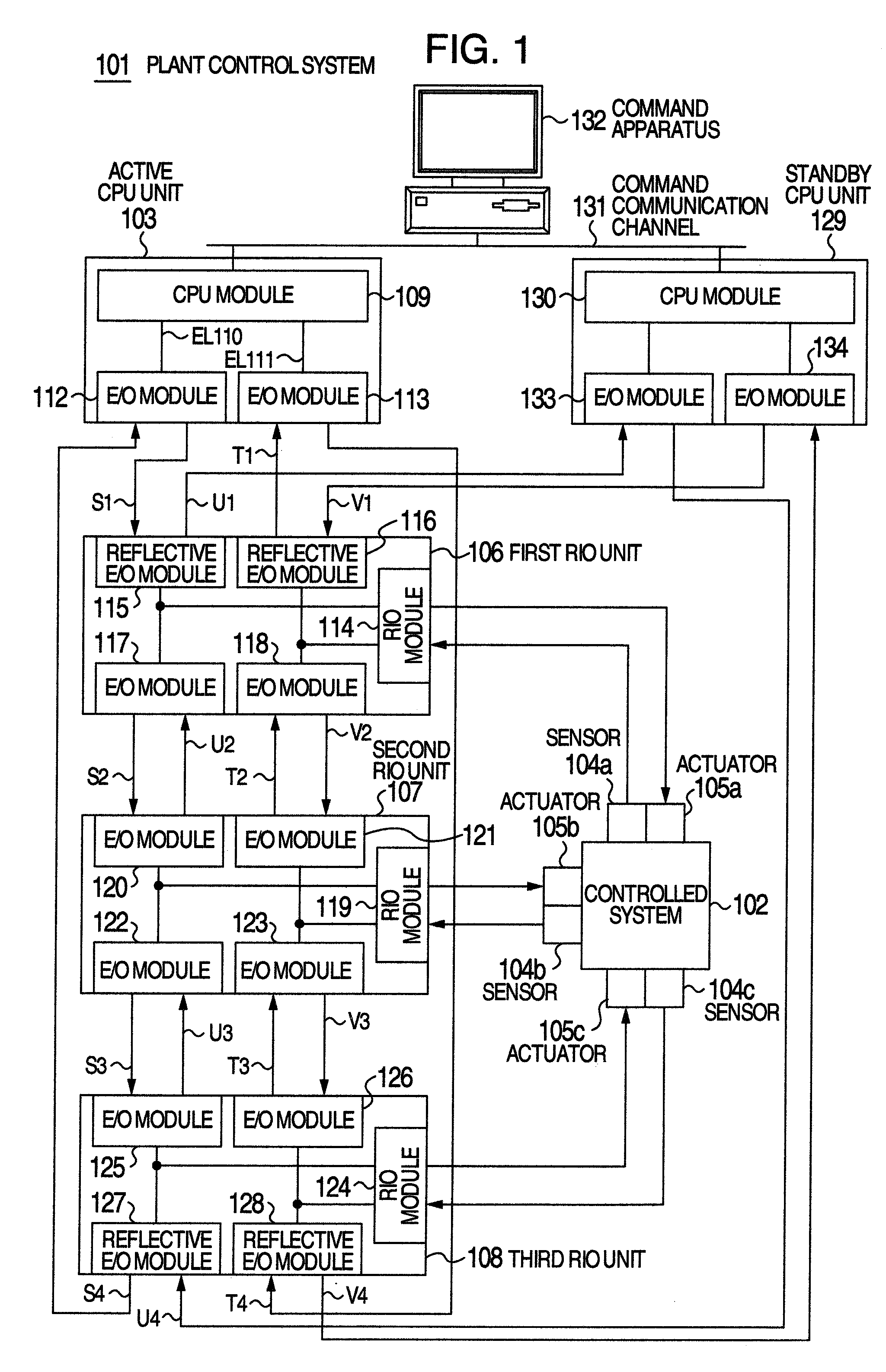
[0050]An overall plant control system as an embodiment of this invention will be described below in reference to FIGS. 1 through 5.

[0051]FIG. 1 shows in block diagram the entire structure of a plant control system as an embodiment of this invention.

[0052]A plant control system 101 serves to perform suitable controls over a controlled system 102.

[0053]The controlled system 102 is controlled by the data frames transmitted by an active CPU 103 and also reflects the signals generated by plural sensors 104a, 104b and 104c installed in a controlled system 102, to the following control cycles where the active CPU unit 103 receives the signals and thereby controls actuators 105a, 105b and 105c.

[0054]As shown in FIG. 1, three remote input / output units (hereafter referred to as RIO units) such as a first RIO unit 106, a second RIO unit 107 and a third RIO unit 108, are disposed between the active CPU 103 and the controlled system 102, as interfaces for the sensors 104a, 104b and...


PUM


Abstract

In the disclosed control system, loops of 1st path and 2nd path are formed connecting an active CPU unit and each of RIO units, the direction of data frame transfer through the loop of 1st path being opposite to that of the data frame transfer through the loop 2nd path. Reflective electro-optical transducer modules are used in the RIO units which are connected with the active CPU unit so that a standby CPU unit can also be connected. Further, the loop of 1st path and the loop of 2nd path are formed connecting the standby CPU module and each of the RIO modules. The data frame transfer directions through the loops connecting the active CPU unit and each of the RIO units are opposite to the data frame transfer directions through the corresponding loops connecting the standby CPU unit and each of the RIO units.

Description

BACKGROUND OF THE INVENTION[0001]This invention relates to a control system and a CPU unit for use in the control system.[0002]In a control system used in a facility such as a steel plant or a nuclear power plant, in which the first priority is to maintain security, extremely high availability is required, the term “availability” used here being defined as an index of how resistive the control system is to a failure, or simply as operation availability. This is because a fatal accident might be incurred if the control system stops operating for some cause.[0003]JP-A-2010-200016 discloses an example of the related conventional art.SUMMARY OF THE INVENTION[0004]According to the conventional control system in general, a single CPU unit which commands a sequence control or a feedback control is connected with a single Remote Input / Output Unit (hereafter referred to as “RIO unit”) which executes a sequence control or a feedback control on the controlled system. Indeed, a single CPU is a ...

Claims


Application Information

Patent Timeline
Patent Type & Authority Applications(United States)
IPC IPC(8): G06F3/00
CPCG05B15/02
Inventor ONOZUKA, AKIHIROSHIMIZU, KATSUHITOOTSUKA, YUSAKUTAHARA, YUKIKOISHIKAWA, MASAKAZUKOBAYASHI, EIJISASAKI, WATARUNAKANO, AKIHIROSEKI, YUUSUKE
Owner HITACHI LTD
Learn More