
Auxiliary handle

a technology of auxiliary handles and handles, applied in the field of auxiliary handles, can solve the problems of compact structure of auxiliary handles, and achieve the effect of compact structur

Active Publication Date: 2011-06-09
HILTI AG
View PDF11 Cites 12 Cited by
  • Summary
  • Abstract
  • Description
  • Claims
  • Application Information

AI Technical Summary

Benefits of technology

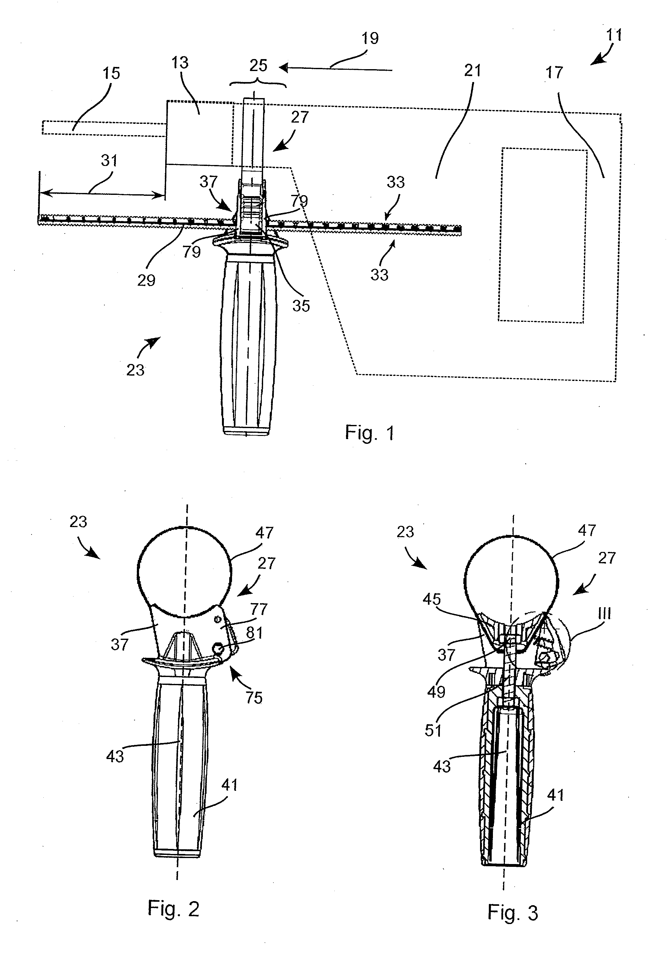
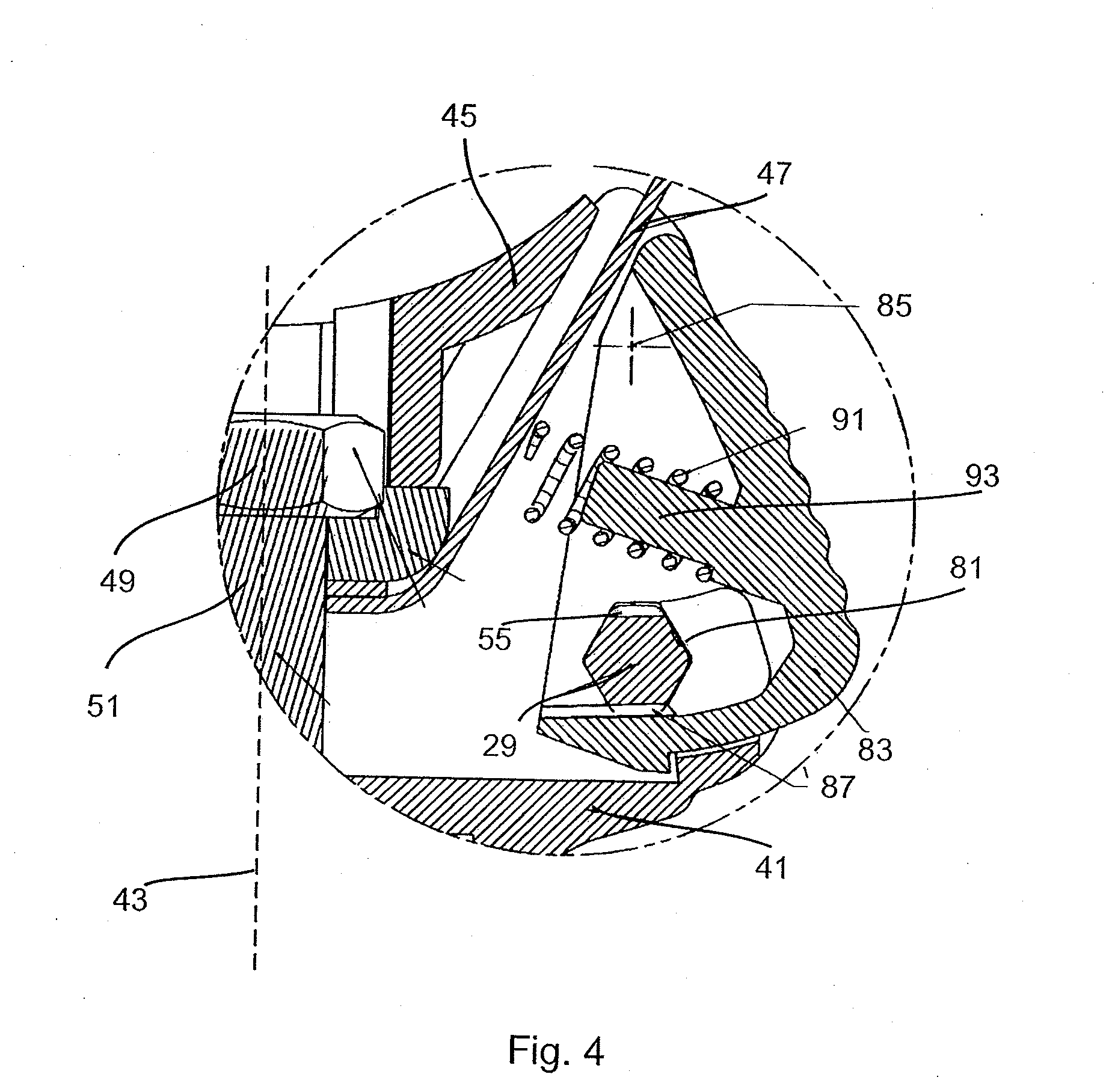
[0003]The auxiliary handle for a hand-held power according to the invention has a handle piece, a fixation means for fixing the auxiliary handle to the hand-held power tool, a rod with at least one set of teeth, and a guide in which the rod is seated longitudinally movably. A locking mechanism has a pawl, a pivot axis about which the pawl can be rotated between a locking position and a release position, and at least one locking tooth on the pawl that engages in a locked position with the set of teeth, and is pivoted out of the guide in a release position. A spring element initially tensions the pawl into the locking position. A distance of the spring element from the pivot axis is less than a distance of the locking tooth from the pivot axis. The arrangement of the spring element between the guide or the locking tooth and the pivot axis allows a particularly compact structure.

Problems solved by technology

One problem is a compact structure of an auxiliary handle.

Method used


Image

  • Auxiliary handle
  • Auxiliary handle
  • Auxiliary handle

Examples


Embodiment Construction

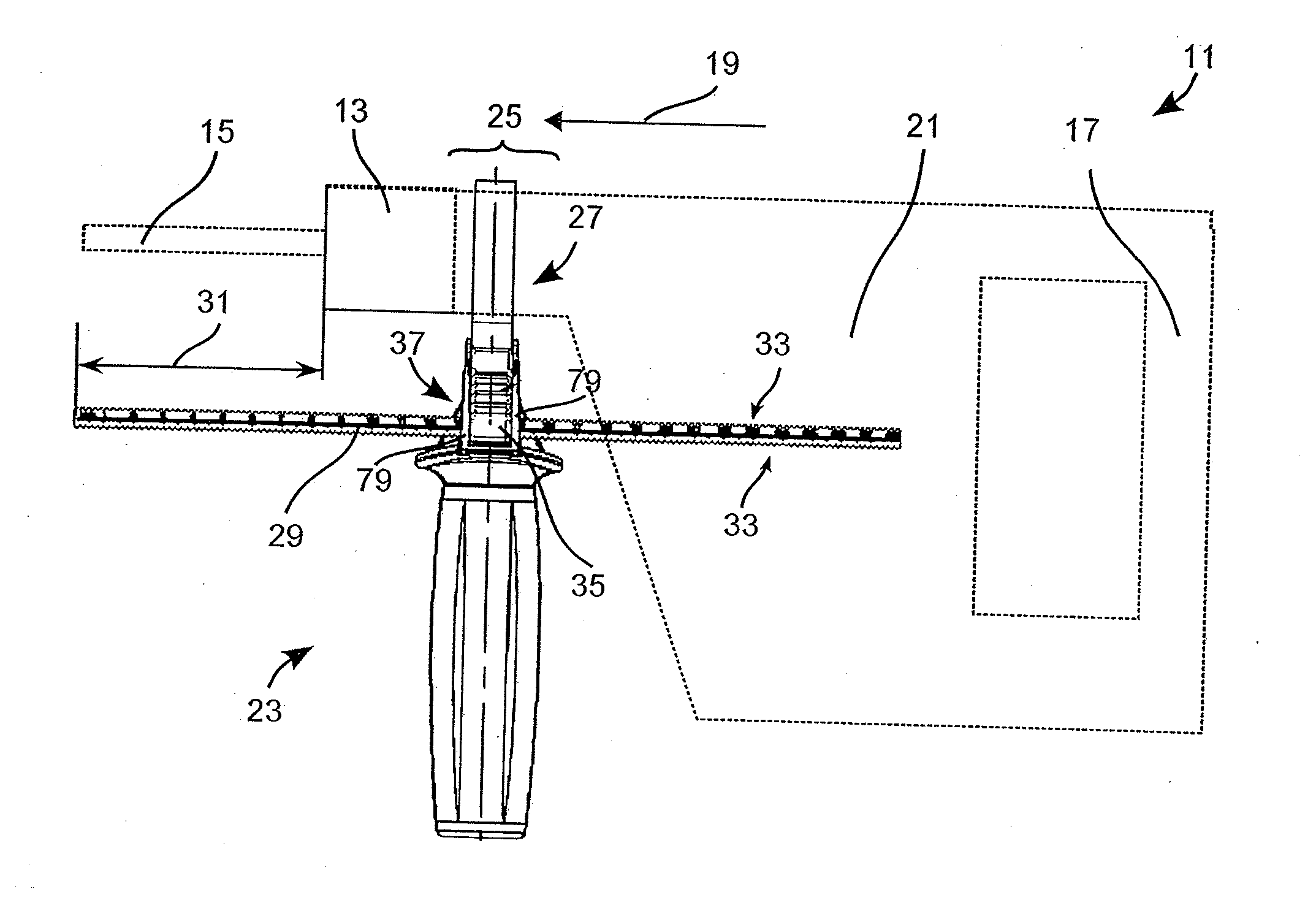
[0022]FIG. 1 shows a drilling machine 11 or a hammer drill as an example of a hand-held power tool. The drilling machine 11 has a tool holder 13 into which a tool 15, a drill bit for example, can be inserted.

[0023]A user can guide the drilling machine 11 in the working direction 19 by means of a main handle 17. The main handle 17 is non-detachably connected to a housing 21 of the drilling machine 11. The user can affix an additional auxiliary handle 23 to the housing 21 if he would like to guide the drilling machine 11 with two hands, and can remove the auxiliary handle 23 if he has no use for it. A fixation area 25 matched to the auxiliary handle 23 is provided on the housing 21 for this purpose. In the illustrated example, the fixation area 25 is provided adjacent to the tool holder 13, and is formed, for example, by a cylindrical contour of the housing 21. The auxiliary handle 23 has an annular fixation means 27 that surrounds the fixation area 25 and is clamped to it.

[0024]An ad...


PUM

PropertyMeasurementUnit
distanceaaaaaaaaaa
symmetry propertiesaaaaaaaaaa
rotational symmetryaaaaaaaaaa

Abstract

An auxiliary handle for a hand-held power tool has a handle piece, a fixation means for fixing the auxiliary handle to the hand-held power tool, a rod with at least one set of teeth, and a guide in which the rod is seated longitudinally movably. A locking mechanism has a pawl, a pivot axis about which the pawl can be rotated between a locking position and a release position, and at least one locking tooth on the pawl that engages in a locked position with the guide, and is pivoted out of the guide in a release position. A spring element initially tensions the pawl into the locking position. A distance of the spring element from the pivot axis is less than a distance of the locking tooth from the pivot axis.

Description

FIELD OF THE INVENTION[0001]The present invention relates to an auxiliary handle. An auxiliary handle for a hand-held drilling machine is known from EP 1 336 446 B1. The auxiliary handle can be removed from the hand-held power tool. A depth stop to indicate to the user that a desired drilling depth has been reached is integrated into the auxiliary handle.DISCLOSURE OF THE INVENTION[0002]One problem is a compact structure of an auxiliary handle.[0003]The auxiliary handle for a hand-held power according to the invention has a handle piece, a fixation means for fixing the auxiliary handle to the hand-held power tool, a rod with at least one set of teeth, and a guide in which the rod is seated longitudinally movably. A locking mechanism has a pawl, a pivot axis about which the pawl can be rotated between a locking position and a release position, and at least one locking tooth on the pawl that engages in a locked position with the set of teeth, and is pivoted out of the guide in a relea...

Claims


Application Information

Patent Timeline
Patent Type & Authority Applications(United States)
IPC IPC(8): B25F5/02
CPCB25F5/026B25F5/003Y10T408/98Y10T408/65Y10T16/4713
Inventor IMASCHEWSKI, JENSWAHLE, QUIRIN
Owner HILTI AG
Learn More