Wooden pallet with nail plates and related methods

Active Publication Date: 2011-06-09
CHEP TECH PTY LTD
View PDF27 Cites 12 Cited by
  • Summary
  • Abstract
  • Description
  • Claims
  • Application Information

AI Technical Summary

Benefits of technology

[0017]Another aspect of the wooden pallet is directed to the nail plates, wherein each nail plate may h

Problems solved by technology

Impacts such as this weaken the pallet and greatly shorten the lifespan of the pallet, thereby causing the palle

Method used


Image

  • Wooden pallet with nail plates and related methods
  • Wooden pallet with nail plates and related methods
  • Wooden pallet with nail plates and related methods

Examples


Embodiment Construction

[0029]The present invention will now be described more fully hereinafter with reference to the accompanying drawings, in which preferred embodiments of the invention are shown. This invention may, however, be embodied in many different forms and should not be construed as limited to the embodiments set forth herein. Rather, these embodiments are provided so that this disclosure will be thorough and complete, and will fully convey the scope of the invention to those skilled in the art. Like numbers refer to like elements throughout, and prime and double prime notations are used to indicate similar elements in alternative embodiments.

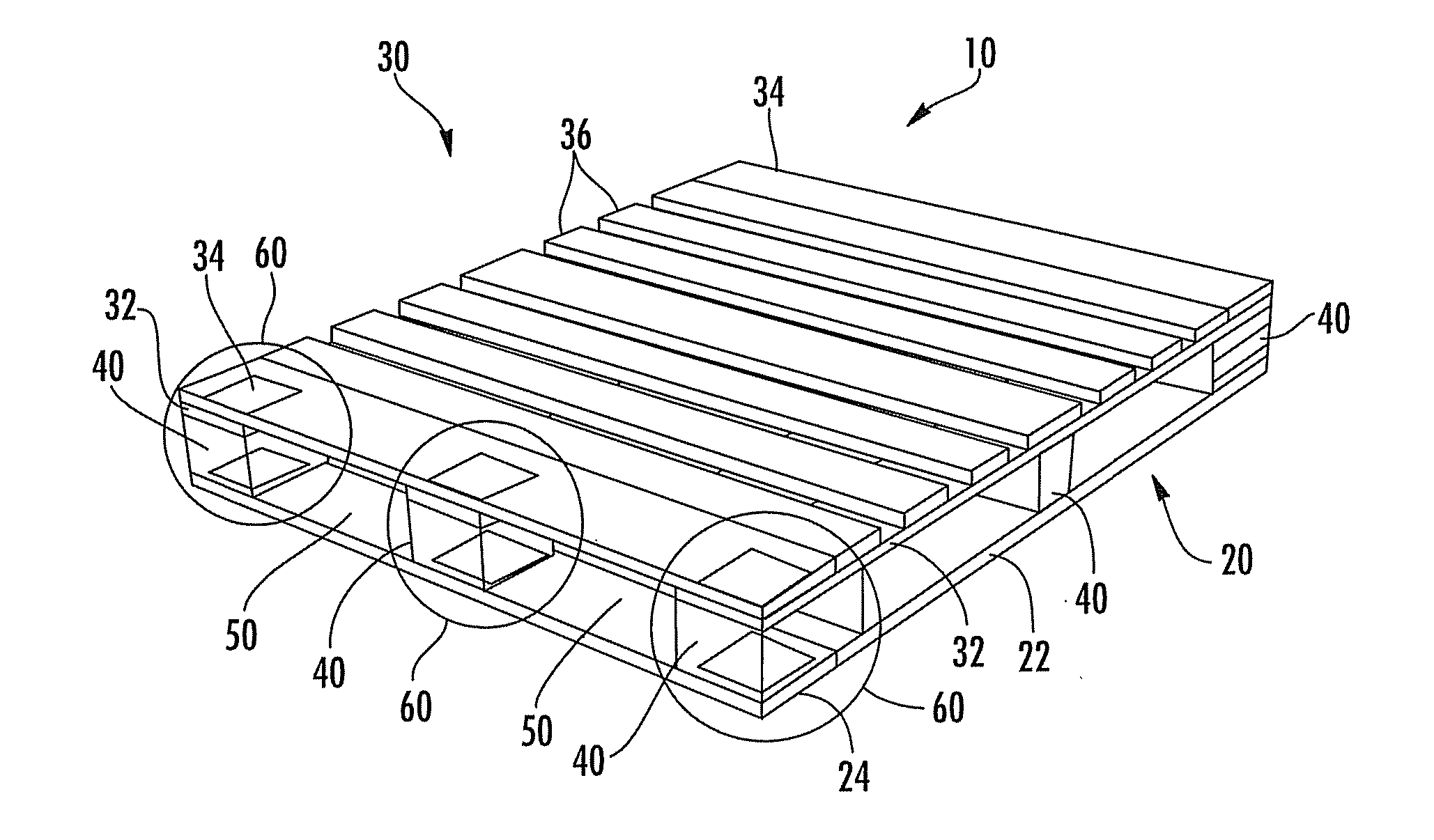
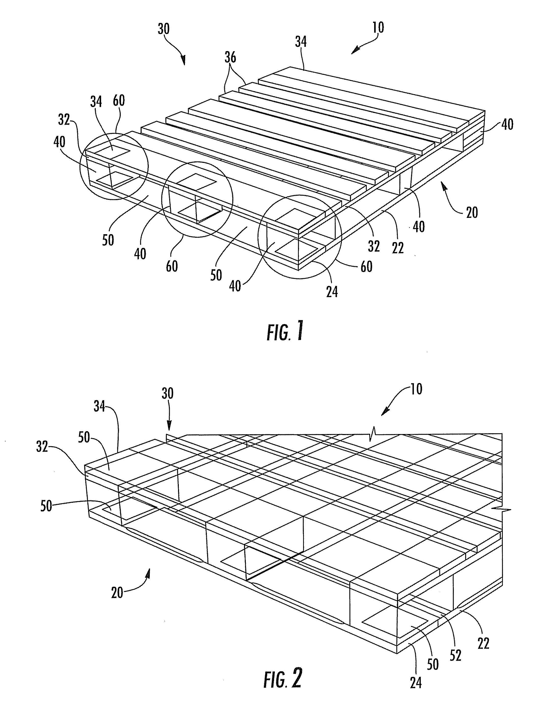
[0030]Referring initially to FIGS. 1-4, a pallet 10 comprises a base layer 20, a cargo layer 30 and a plurality of support blocks 40. The support blocks 40 are coupled between the base and cargo layers 20, 30 and define a space 50 therebetween for receiving the lifting members of material handling equipment, such as fork lift tines from a forklift.

[0031]T...


PUM


Abstract

A wooden pallet includes a base layer, and a cargo layer. The cargo layer includes a pair of spaced apart connector boards, and a pair of spaced apart end deck boards orthogonal to the pair of connector boards. Respective ends of the pair of end deck boards overlap respective ends of the pair of connector boards. Nail plates are coupled between the respective ends of the pair of connector boards and the respective ends of the pair of end deck boards. Each nail plate has a first surface having projections extending outwards therefrom and embedded into one of the end deck boards, and a second surface opposite the first surface devoid of any projections and contacting an end of one of the connector boards. Spaced apart support blocks are between the base layer and the pair of connector boards in the cargo layer, and form a gap therebetween for receiving a lifting member.

Description

RELATED APPLICATION[0001]This application claims the benefit of U.S. Provisional Application Ser. No. 61 / 267,664 filed Dec. 8, 2009, the entire contents of which are incorporated herein by reference.FIELD OF THE INVENTION[0002]The present invention relates to the field of pallets, and more particularly, to a wooden pallet having an improved resilience to impacts from material handling equipment, and to related methods for making the same.BACKGROUND OF THE INVENTION[0003]Conventional wood pallets include a base layer and a cargo layer separated therefrom by support blocks. Traditionally, the base and cargo layers respectively have end deck boards assembled on connector boards that run the full length or width of the pallet. The end deck boards are nailed through the connector boards into the support blocks to build the primary structure of the pallet. The end deck boards are also known as lead boards, and the connector boards are also known as stringer boards.[0004]To move the wooden...

Claims


Application Information

Patent Timeline
IPC IPC(8): B65D19/31B23P11/00
CPCB65D2519/00029Y10T29/49833B65D2519/00099B65D2519/00273B65D2519/00293B65D2519/00323B65D2519/00373B65D2519/00572B65D19/0095F16B15/0046B65D2519/00129B65D2519/00298B65D2519/00333B65D2519/00437B65D2519/00442B65D2519/00064B65D19/14
Inventor BRANDT, KENLANTZ, DAN
Owner CHEP TECH PTY LTD
Why Eureka
Try Eureka