Block Configuration for Large Scale Membrane Distillation

a membrane distillation and block configuration technology, applied in the direction of membranes, general water supply conservation, separation processes, etc., can solve the problem of complex manifolding systems

Inactive Publication Date: 2011-06-09
SIEMENS IND INC
View PDF102 Cites 49 Cited by
  • Summary
  • Abstract
  • Description
  • Claims
  • Application Information

AI Technical Summary

Benefits of technology

[0007]The present invention seeks to provide a membrane distillation system having co

Problems solved by technology

This may require complex manifolding sys

Method used


Image

  • Block Configuration for Large Scale Membrane Distillation
  • Block Configuration for Large Scale Membrane Distillation
  • Block Configuration for Large Scale Membrane Distillation

Examples


Embodiment Construction

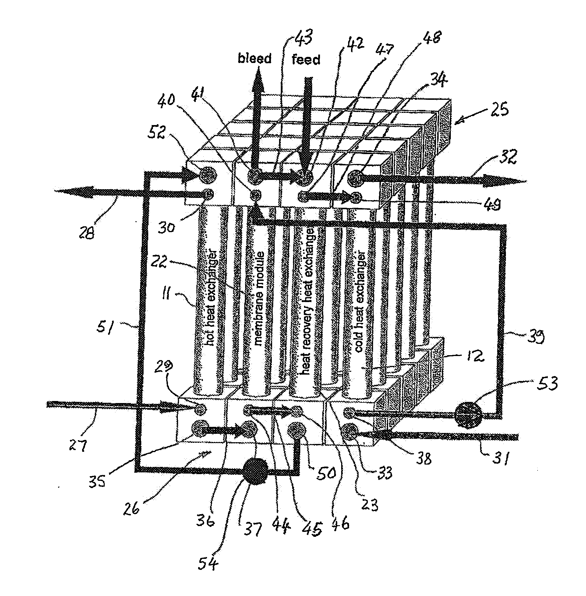
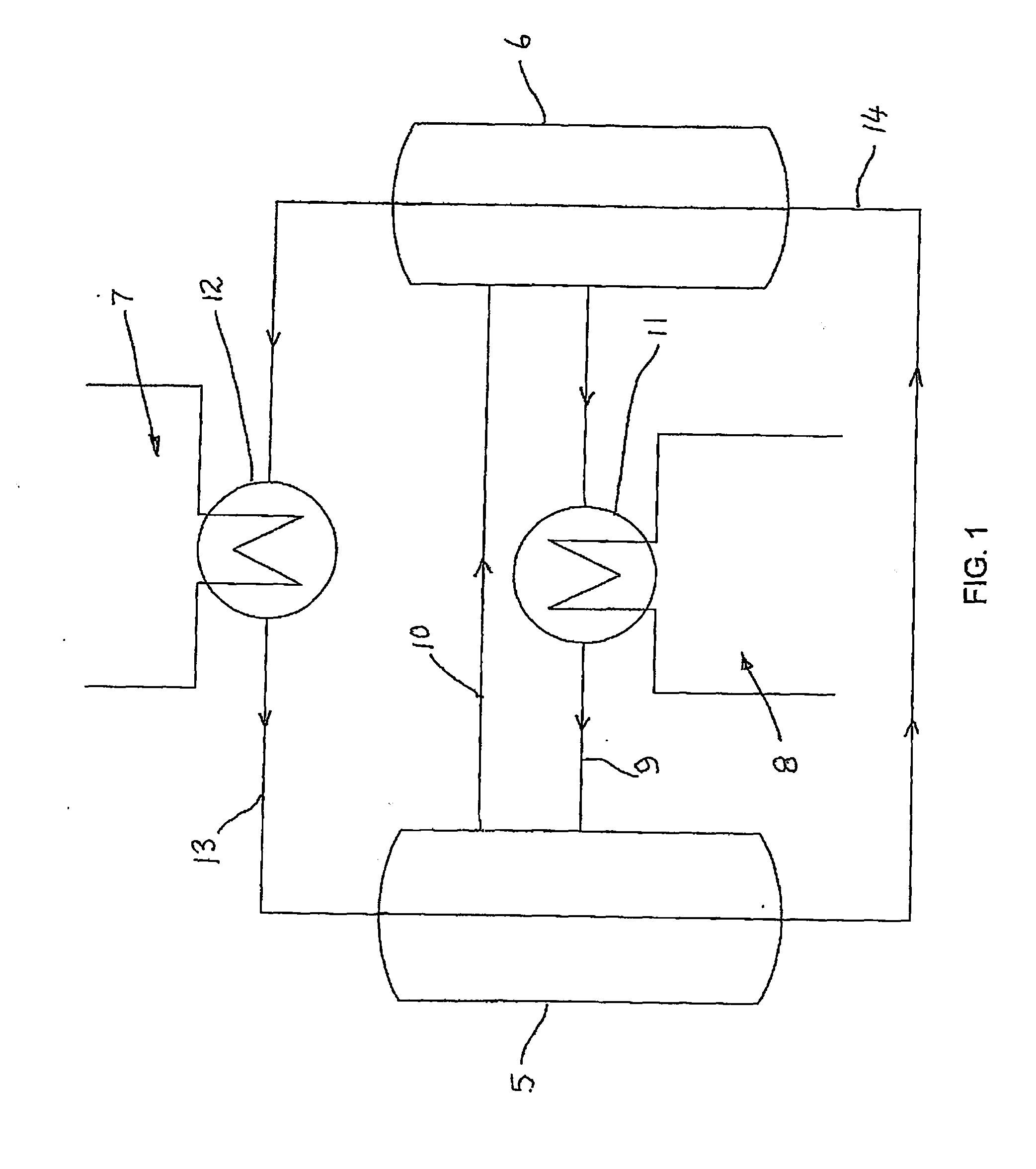
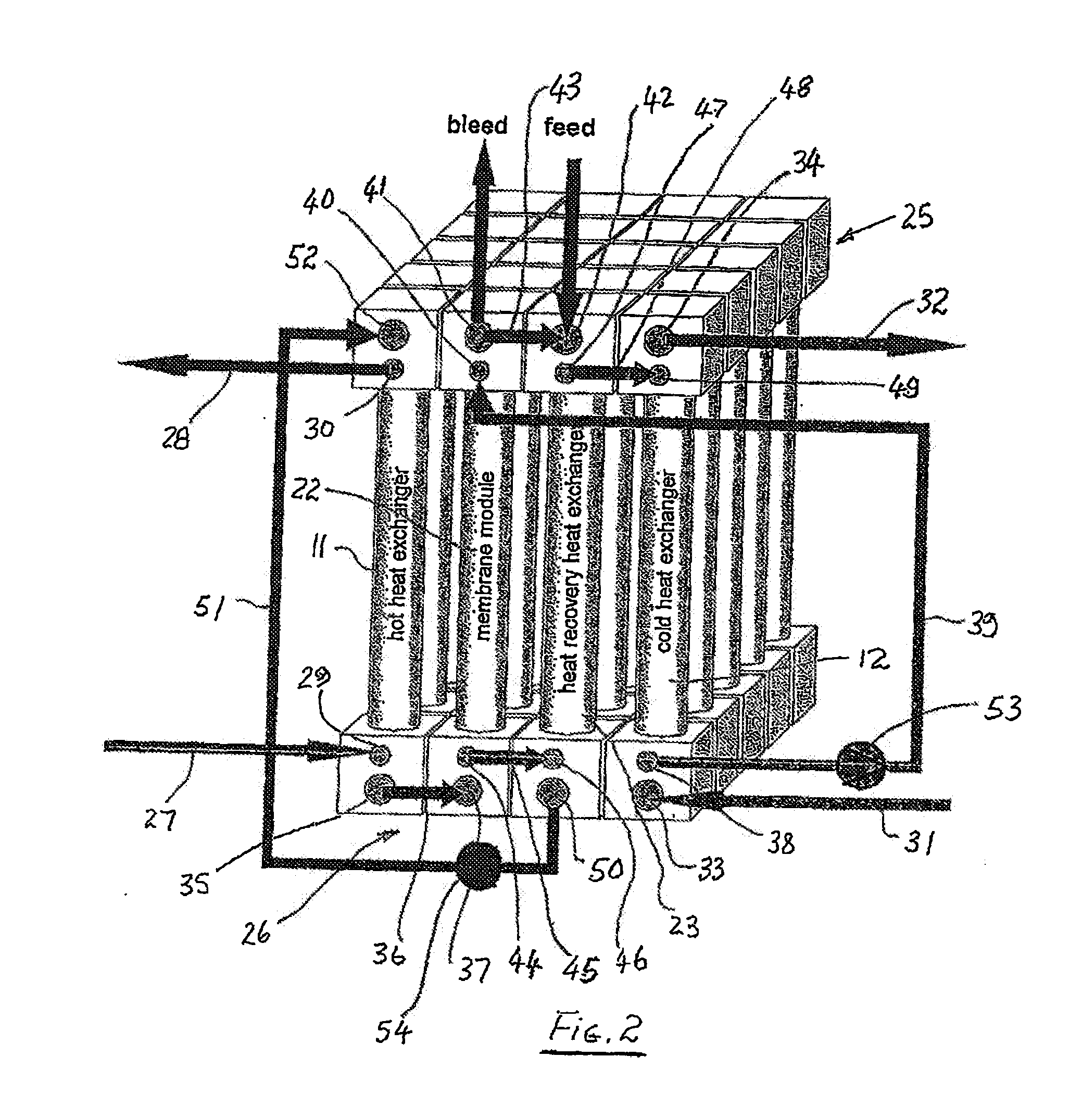
[0019]Referring to FIG. 1 there is shown a schematic diagram of a typical membrane distillation system. The system illustrated is a direct contact membrane distillation system where both the warm vaporising stream and the cold condensate stream are in direct contact with the membrane by either flowing through the membrane lumen or along the outside of the membranes. The membranes are hollow fibre membranes arranged in modules, however, it will be appreciated that any form of membrane may be used such as sheet, tubular, plate or mat types. It will be also appreciated that the membranes may be adapted to operate as one of the further forms of membrane distillation system described above, for example, the outer surfaces of the membranes could be separated from the fluid flow by a suitable air-gap.

[0020]It will be appreciated that the system is configured for use in both membrane distillation applications and heat exchanger distillation applications. The operating conditions of the two ...


PUM


Abstract

Embodiments of the present invention seek to provide a membrane distillation system having compact design and simplified connection system for fluid flow paths used in the system. According to one aspect, a membrane distillation system includes at least one membrane module and at least one like configured heat exchanger module, the modules being supported and connected to like configured manifold devices for providing fluid communication between said modules.

Description

TECHNICAL FIELD[0001]The present invention relates to membrane distillation systems and more particularly to an improved manifold configuration for large-scale membrane distillation systems.BACKGROUND OF THE INVENTION[0002]Membrane distillation differs from other distillation techniques such as multi-stage flash, multiple effect distillation and vapour compression in that a non-selective, porous membrane is used. The membrane forms a separation between the warm, vaporising retentate stream and the condensed product, the distillate stream. A suitable choice of membrane material (usually polypropylene, polyethylene or polytetraflorethene) is thus required to ensure the membrane pores are not wetted by the liquid and only vapour passes through the membrane.[0003]Membrane distillation was first described in the mid sixties in an application to improve the efficiency of seawater desalination by the use of an air-filled porous hydrophobic membrane. The method concerned was a so-called dir...

Claims


Application Information

Patent Timeline
IPC IPC(8): B01D61/36
CPCB01D61/364B01D2313/10B01D65/00B01D2313/38B01D2313/12Y02A20/131B01D2313/221
Inventor MULLER, HEINZ-JOACHIMTUN, CHAN MYA
Owner SIEMENS IND INC
Why Eureka
Try Eureka