
Capacity loaded planar antenna with short stubs

a planar antenna and short stub technology, applied in the direction of antennas, antenna earthings, antenna details, etc., can solve problems such as complicated structure, and achieve the effects of small size, wide bandwidth, and low postur

Inactive Publication Date: 2011-06-09
KOKUSA ELECTRIC CO LTD
View PDF3 Cites 5 Cited by
  • Summary
  • Abstract
  • Description
  • Claims
  • Application Information

AI Technical Summary

Benefits of technology

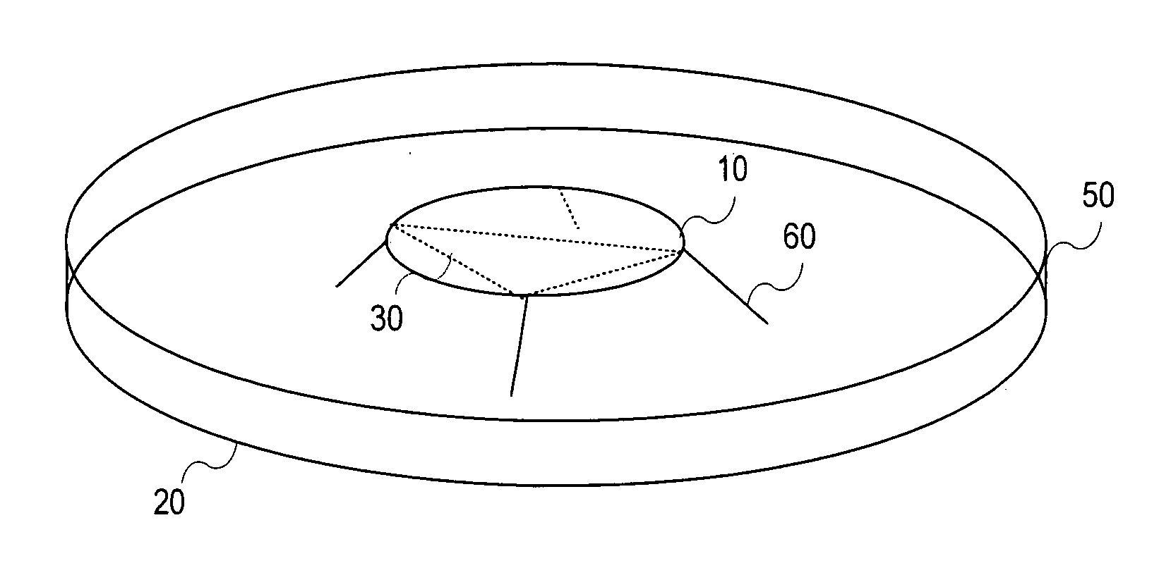
[0025]The present invention has been developed in view of the above situation, and an object thereof is to provide a capacity loaded planar antenna with short stubs which can acquire a small size and a low posture, can realize a wider bandwidth and can be tuned to a plurality of frequencies.
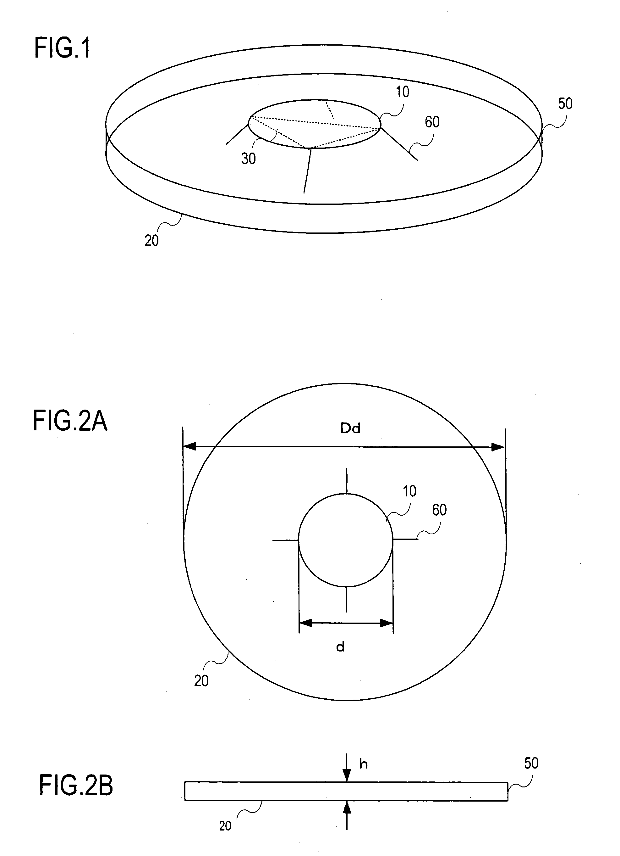
[0026]To solve the above problem of the conventional example, according to the present invention, there is provided a capacity loaded planar antenna with short stubs, comprising: a base plate; an antenna element disposed in parallel with the base plate; a plurality of short stubs which connect the antenna element to the base plate; and a side wall formed along the end portion of the base plate, which produces an effect that it is possible to acquire a small size and a low posture and realize a wider bandwidth.
[0027]According to the present invention, in the above capacity loaded planar antenna with the short stubs, a length of the short stubs is varied to vary a resonance frequency, which produces an effect that the antenna can be tuned to a plurality of frequencies.
[0028]According to the present invention, in the above capacity loaded planar antenna with the short stubs, the short stubs are formed integrally with the antenna element, and have a foldable plate-like shape, which produces an effect that the constitution can be simplified to facilitate manufacturing.

Problems solved by technology

However, in the above conventional wideband antenna, to decrease an installation area of the antenna, a base plate needs to be small-sized, and the antenna needs to have a low posture, but to match with a power supply line over a wide bandwidth, the size of the base plate has to be changed, and the antenna needs to be tuned to a plurality of frequencies, which causes a problem that the constitution becomes complicated.

Method used


Image

  • Capacity loaded planar antenna with short stubs
  • Capacity loaded planar antenna with short stubs
  • Capacity loaded planar antenna with short stubs

Examples


Embodiment Construction

[0045]An embodiment of the present invention will be described with reference to the drawings.

Summary of Embodiment

[0046]A capacity loaded planar antenna with short stubs according to the embodiment of the present invention comprises a base plate, an antenna element, a plurality of short stubs which connect the antenna element to the base plate, and a side wall formed along the end portion of the base plate, which can acquire a small size and a low posture and realize a wider bandwidth.

[0047]Moreover, according to the capacity loaded planar antenna with the short stubs of the embodiment of the present invention, in the above constitution, a length of the short stubs can be varied, a resonance frequency can be varied and the antenna can be tuned to a plurality of frequencies.

[0048]Furthermore, according to the capacity loaded planar antenna with the short stubs of the embodiment of the present invention, in the above constitution, the short stubs are formed integrally with the anten...


PUM


Abstract

Provided is a capacity loaded planar antenna with short stubs that can be brought to a small size and a low profile, achieves wider bandwidth, and can be tuned to multiple frequencies. A capacity loaded planar antenna with short stubs that has a simple structure and can be easily manufactured includes a base plate, an antenna element disposed so as to be parallel to the base plate, a plurality of short stubs that connect the antenna element to the base plate, and a side wall formed on the end of the base plate. The capacity loaded planar antenna achieves wider bandwidth with the small size and low profiled, can be tuned to multiple frequencies by adjusting the length of the short stubs, and uses plate-shaped foldable short stubs that are integrated with the antenna element.

Description

[0001]This is a Continuation of PCT / JP2009 / 002310 filed May 26, 2009 and published in Japanese, which has a priority of Japanese no. 2008-139617 filed May 28, 2008, hereby incorporated by reference.BACKGROUND OF THE INVENTION[0002]1. Field of the Invention[0003]The present invention relates to a small-sized antenna used in a weak electric field area of a base station antenna for mobile communication and more particularly, it relates to a capacity loaded planar antenna with short stubs which can achieve a wider bandwidth without changing a size of a base plate.[0004]2. Description of the Related Art[0005]In an indoor transponder for mobile communication installed on a ceiling or the like to be used, an omnidirectional, low-posture and small-sized wideband antenna is used.[0006]In a capacity loaded monopole antenna obtained by lowering the posture of an omnidirectional monopole antenna, a plurality of posts can be arranged to match with a power supply line.[0007][Constitution of Conve...

Claims


Application Information

Patent Timeline
Patent Type & Authority Applications(United States)
IPC IPC(8): H01Q1/48
CPCH01Q9/0421H01Q1/48
Inventor SUTO, MASAKIMATSUBARA, RYOJIMICHISHITA, NAOBUMI
Owner KOKUSA ELECTRIC CO LTD
Learn More