Image capturing apparatus and method and program for controlling same

a technology of image capturing and image, applied in the field of image capturing apparatus, can solve the problems of difficult to obtain a correlation from the result of addition, inappropriate computation result,

Active Publication Date: 2011-06-09
CANON KK
View PDF4 Cites 22 Cited by
  • Summary
  • Abstract
  • Description
  • Claims
  • Application Information

AI Technical Summary

Benefits of technology

[0009]The present invention has been devised in view of the circumstances set forth above and makes it possible to perform suitable focus detection with regard to a subject under diminished brightness.

Problems solved by technology

On the other hand, when such processing is executed, there are instances where an inappropriate result of computation is obtained if the same subject does not appear at each pixel that is to undergo synthesis.
Further, if an image that can be approximated by a line that is oblique with respect to the direction of correlation appears, there are instances where it is difficult to obtain a correlation from the result of addition.

Method used


Image

  • Image capturing apparatus and method and program for controlling same
  • Image capturing apparatus and method and program for controlling same
  • Image capturing apparatus and method and program for controlling same

Examples


first embodiment

[0037]FIGS. 1 to 15 are diagrams useful in describing a first embodiment of the present invention and reference will be made to these drawings to describe the first embodiment.

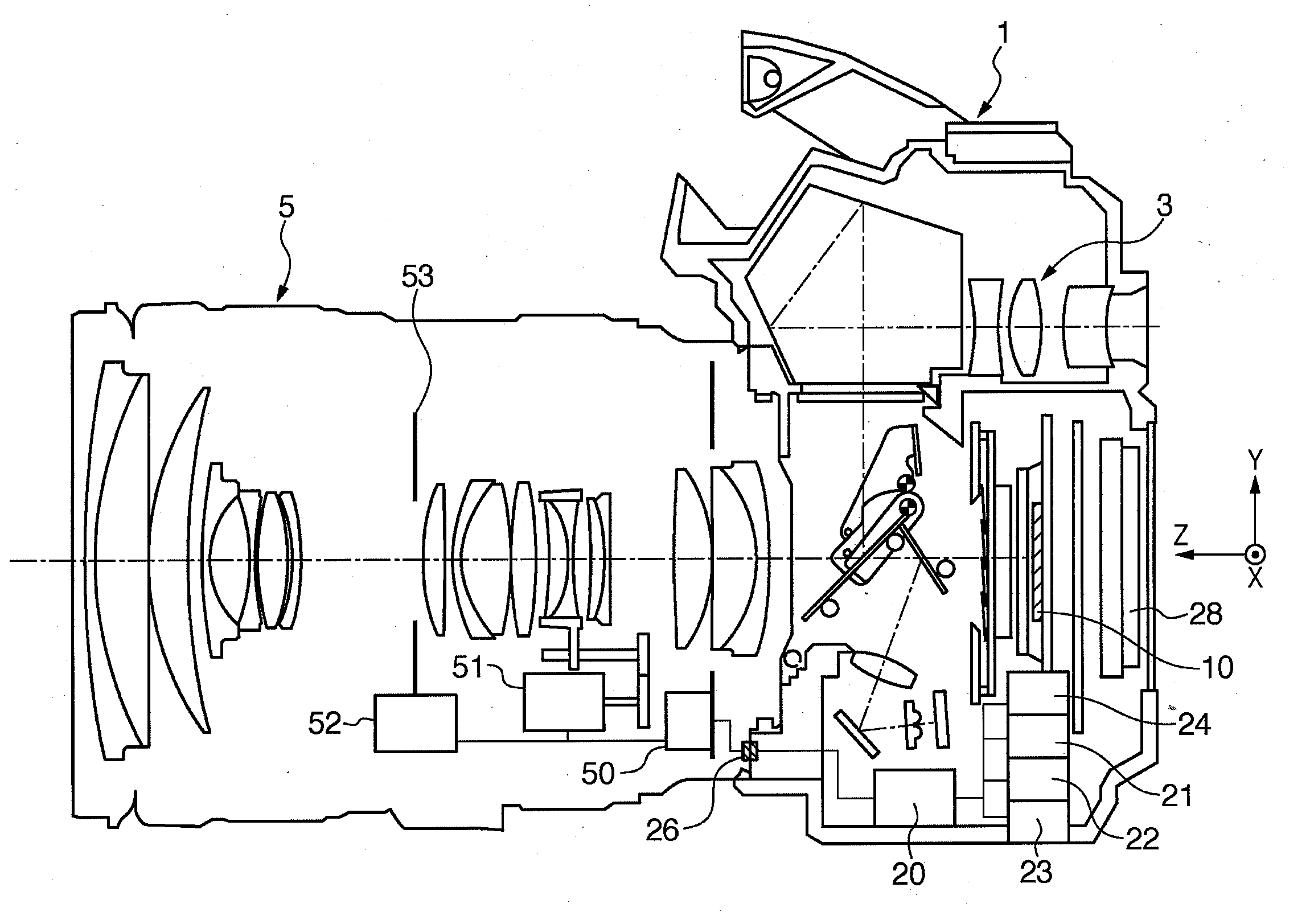
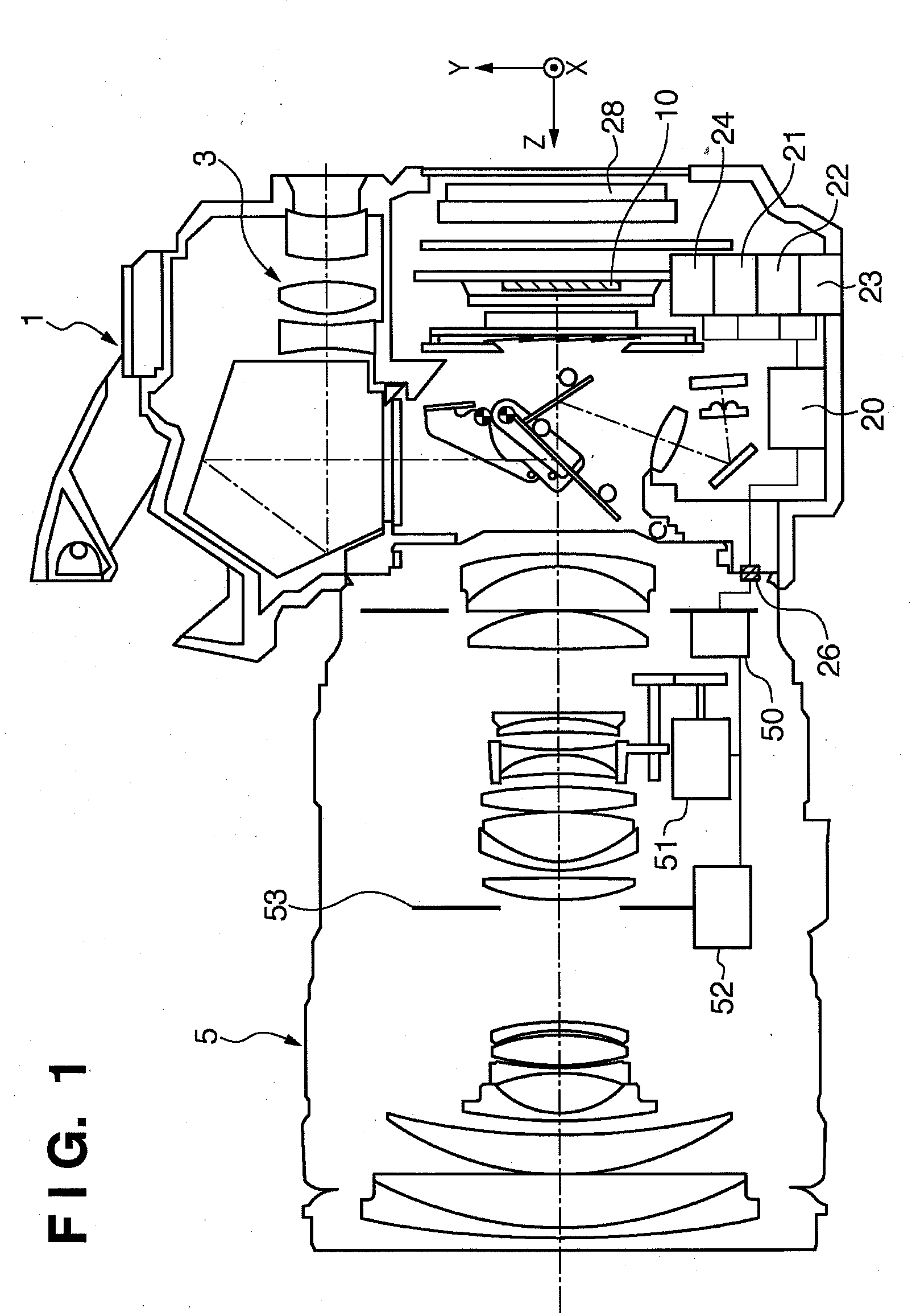
[0038]FIG. 1 is a sectional view of a camera equipped with a focus detection apparatus according to this embodiment.

[0039]As shown in FIG. 1, an image sensor (solid-state image sensing device) 10 is disposed in the image plane of a shooting lens (photographic optical system) 5 of a digital still camera 1. The digital still camera 1 includes a CPU 20 for controlling the overall camera, an image sensor control circuit 21 for driving and controlling the image sensor 10, and an image processing circuit 24 for applying image processing to an image signal captured by the image sensor 10. The digital still camera 1 further includes an eyepiece lens 3 for observing the image of a subject, a memory circuit 22 for recording the image captured by the image sensor 10, and an interface circuit 23 for outputting the image, ...

second embodiment

[0098]FIGS. 16 and 17 are diagrams useful in describing a second embodiment of the present invention and reference will be had to these drawings to describe the first embodiment.

[0099]FIG. 16 is a sectional view of a camera equipped with a focus detection apparatus according to this embodiment. As shown in FIG. 16, an image sensor (solid-state image sensing device) 10 is disposed in the image plane of a shooting lens (photographic optical system) 5 of a digital still camera 1. The electrical configuration of the processing circuitry, etc., is similar to that of the first embodiment and need not be described again.

[0100]When the operator has decided the composition of the photograph using the apparatus shown in FIG. 16, the optical path is changed by a quick-return mirror 200 and light is introduced to the eyepiece lens 3 for observing the image of the subject. At the same time, the quick-return mirror 200 becomes a half-reflector and the remaining light is introduced to a focus dete...


PUM


Abstract

An image capturing apparatus includes an image sensor provided in the neighborhood of an image plane of a photographing optical system for forming the image of a subject; pupil dividing member for forming images of a pair of light beams that have passed through different pupil regions of the photographing optical system; focus detection sensors arranged two-dimensionally for photoelectrically converting images of the pupil dividing member; and a correlation calculation unit which, in order to obtain one focus measurement value from one pair of two-dimensional images generated by the focus detection sensors and extending in the pupil dividing direction of the pupil dividing member and in a direction perpendicular to the pupil dividing direction, calculates the correlation between the pair of two-dimensional images while shifting the pair of two-dimensional images in the pupil dividing direction.

Description

TECHNICAL FIELD[0001]The present invention relates to an image capturing apparatus having an autofocus detection function.BACKGROUND ART[0002]Improvements in the performance of focus detection systems in recent years have been accompanied by many proposals relating to so-called multi-point focus detection systems of multi-point focusing type in which range finding is possible at multiple points within a viewfinder. In a multi-point detection apparatus that performs multi-point focusing by utilizing the principle of phase-difference autofocusing, use is made of a method that involves acquiring a pair of image signals corresponding to respective focus-measurement points, performing a correlation computation and computing a defocus amount from the phase difference between the signals.[0003]The specification of Japanese Patent Application Laid-Open No. 5-11178 discloses a technique for selecting defocus amounts, which are in an order designated by counting from the short-distance side, ...

Claims


Application Information

Patent Timeline
Patent Type & Authority Applications(United States)
IPC IPC(8): H04N5/232
CPCG02B7/28G02B7/34G03B13/36H04N5/372H04N5/23212H04N5/23219G03B19/12H04N23/611H04N25/71
Inventor KIMURA, MASAFUMI
Owner CANON KK
Why Eureka
Try Eureka