Method for depth resolved wavefront sensing, depth resolved wavefront sensors and method and apparatus for optical imaging

a technology of depth resolution and wavefront, applied in the field of wavefront sensing and to wavefront sensors, can solve the problems of acquiring aberration information, unable to provide depth resolved wavefront information, and disregarded variation of aberration with depth, so as to reduce the scope of eliminating stray reflections, improve the attenuation of stray reflections, and double the strength of interference signals

Active Publication Date: 2011-06-09
PODOLEANU ADRIAN +1
View PDF4 Cites 83 Cited by
  • Summary
  • Abstract
  • Description
  • Claims
  • Application Information

AI Technical Summary

Benefits of technology

[0024]The invention discloses devices and methods which can provide depth resolved aberration information, or at least are less sensitive to stray reflections coming from other depths than those inside the object. WFSs less sensitive to reflections from lenses are needed, with the advantage that lenses could be used in the interface optics, which make all optics layout more compact. In the same spirit, if the WFS is less sensitive to cornea reflections, then perfect on-axis imaging becomes feasible, advantageous for aberrations-free imaging systems. The invention provides improved results, less sensitive to the chromatic aberration.
[0029]In a second aspect, improved attenuation of the stray reflections is achieved by using balance detection, where two photodetectors, two smart chips or two CMOS or CCD arrays are used, whose signals are deducted to double the strength of the interference signal and cancel the common mode signals.
[0030]In all these embodiments, depth resolved aberrations are obtained by superposing a reference beam over the object beam returned from the object. The reference beam is derived from the same source as that providing illumination of the object to produce the aberration mapping. If the source used has low coherence, then interference is produced only when the optical path difference (OPD) between the object beam and the reference beam is less than the coherence length of the source. The coherence gating principle is achieved either by using a broadband source and TD-OCT or a swept source and SS-OCT. The coherence gating may be used to provide depth resolved aberration information from the sample object, or it may be used for the reduced scope of eliminating stray reflections from the interface optics.

Problems solved by technology

However, the method cannot provide depth resolved wavefront information due to the low numerical aperture associated to each beamlet created by the SLM.
All the WFSs presented and the systems using them have the disadvantage that for thick objects, the variation of aberration with depth is disregarded.
A general problem with prior art configurations is that they acquire aberration information from a large depth range of the object investigated.
On the other hand, even if depth resolved aberration information was provided, the OCT method employed cannot be used in generating a corrected OCT image depending on the variation of aberrations with depth, as the SD-OCT is based on collecting A-scans under a fixed focus.
As another disadvantage of prior art is that WFSs use sensitive photodetectors or arrays of photodetectors which are easily disturbed by stray reflections in the optics.
Therefore, spatial filters are used, which are not 100% functional, i.e. they do not eliminate the reflections from the different interfaces or from the cornea totally.
In this case, the beam used for the WFS cannot be shared by the imaging instrument, because the imaging beam has to cross the middle of the pupil at different angles.
The problem of stray reflections determines the use of single path correction configurations, where a thin beam is sent to the eye and aberrations are picked up by the emerging beam coming out of the eye.
Also, in double path correcting configurations of fundus cameras, SLOs or OCTs which use lenses between the scanners and the eye, the stray reflections from the lenses affect the WFSs.
Therefore, curved mirrors are preferred to lenses with the disadvantage of increased set-up size and cost.
The time to work out the interference signal is relatively high and such a procedure is subject to cross talk between pixels, which alters the phase information.
These deficiencies restricted the development of the method.
Imaging and wavefront sensing at the same time or with the same beam is not possible.
A major problem with the prior wavefront sensing technology, with or without coherence gating, is that the information is acquired and provided en-face.

Method used


Image

  • Method for depth resolved wavefront sensing, depth resolved wavefront sensors and method and apparatus for optical imaging
  • Method for depth resolved wavefront sensing, depth resolved wavefront sensors and method and apparatus for optical imaging
  • Method for depth resolved wavefront sensing, depth resolved wavefront sensors and method and apparatus for optical imaging

Examples


Embodiment Construction

LRT / CG-WFS

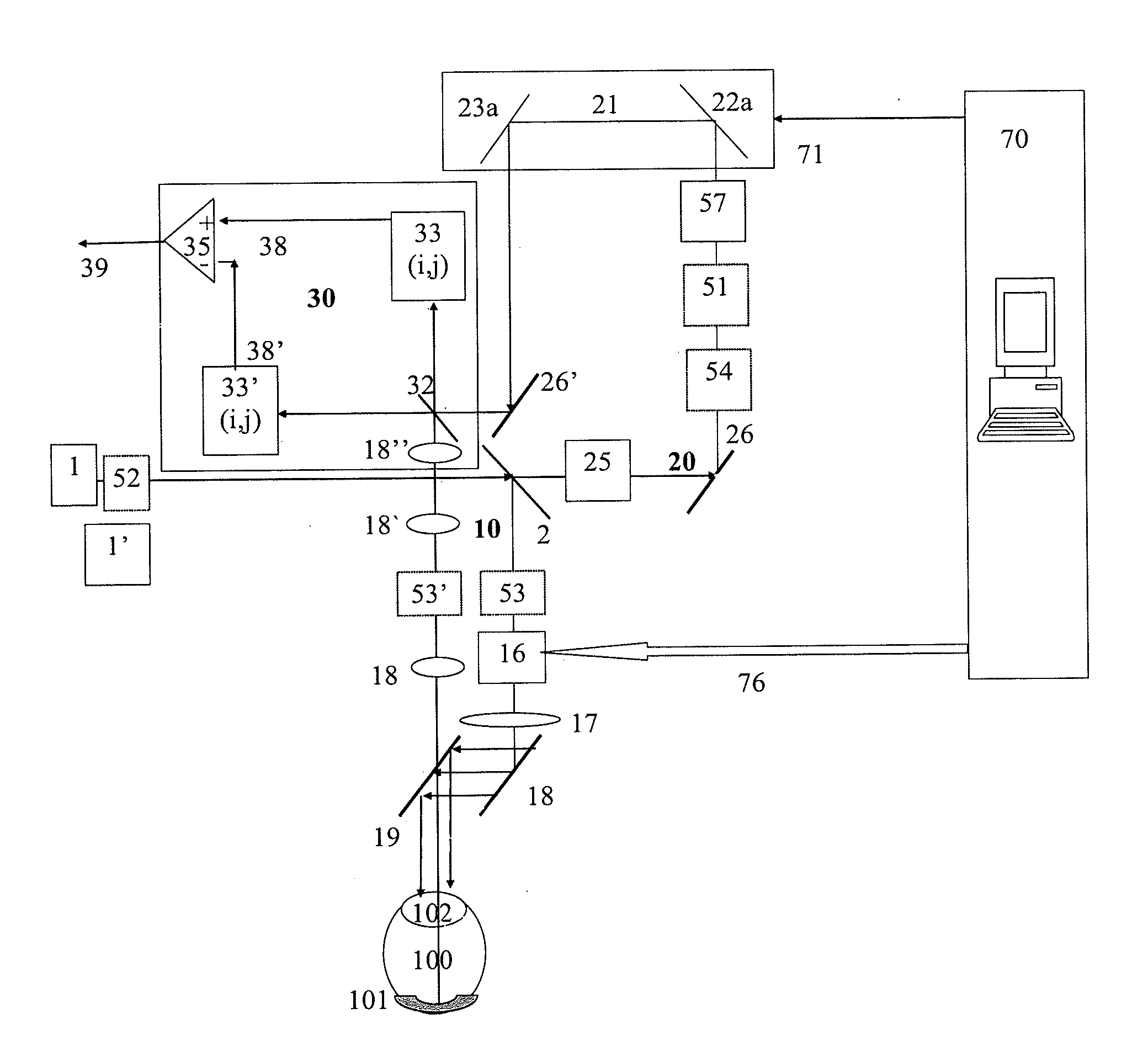
[0054]FIG. 1 discloses a first embodiment of the present invention. A low coherence interferometry principle is incorporated into a first embodiment of a WFS, operating according to the LRT method.

[0055]Light from a low coherent optical source, 1, is split by a splitter 2 towards a XY scanning means 16, which transversally scans the output beam via an interface optics 17, a mirror 18, and a splitter 19, over the cornea aperture, 102, of the eye 100, to focus on the retina 101. The blocks 16 and 17 are shown separately, however they could be interleaved, like the line scanner, a galvo-mirror, a piezo, an acousto-optic deflector, etc, followed by lenses or curved mirrors, and then by a frame scanner consisting of one of the possible means of scanning known. The scanning means 16 and interface 17 could also be implemented using a spatial light modulator (SLM), such as an addressable liquid crystal digital spatial modulator or other means known in the art. Light returns from t...


PUM


Abstract

Methods and devices are disclosed for acquiring depth resolved aberration information using principles of low coherence interferometry and perform coherence gated wavefront sensing (CG-WFS). The wavefront aberrations is collected using spectral domain low coherence interferometry (SD-LCI) or time domain low coherence interferometry (TD-LCI) principles. When using SD-LCI, chromatic aberrations can also be evaluated. Methods and devices are disclosed in using a wavefront corrector to compensate for the aberration information provided by CG-WFS, in a combined imaging system, that can use one or more channels from the class of (i) optical coherence tomography (OCT), (ii) scanning laser ophthalmoscopy, (iii) microscopy, such as confocal or phase microscopy, (iv) multiphoton microscopy, such as harmonic generation and multiphoton absorption. In particular, a swept source (SS) is used that drives both an OCT channel and a coherence gated wavefront sensor, where:a) both channels operate according to SS-OCT principles;b) OCT channel integrates over at least one tuning scan of the swept source to provide a TD-OCT image of the object;c) CG-WFS integrates over at least one tuning scan of the swept source to provide an en-face TD-OCT mapping of the wavefront.For some implementations, simultaneous and dynamic aberration measurements / correction with the imaging process is achieved. The methods and devices for depth resolved aberrations disclosed, will find applications in wavefront sensing and adaptive optics imaging systems that are more tolerant to stray reflections from optical interfaces, such as reflections from the microscope objectives and cover slip in microscopy and when imaging the eye, the reflection from the cornea.

Description

FIELD OF THE INVENTION[0001]The present invention relates to a method of wavefront sensing and to wavefront sensors with enhanced performance and to a method using the same in an optical mapping apparatus which can be used to supply high resolution images from essentially transparent objects or tissue via aberrated paths.[0002]Methods and devices are presented for enhancing the performance of wavefront sensors using principles of low coherence interferometry (LCI). These wavefront sensors can operate under large stray reflections in the optics and therefore lead to simplification of adaptive optics (AO) assisted imaging instruments and to improvement of their performance. Solutions are presented for optical imaging configurations employing such sensors to control a wavefront corrector in accordance with the aberration information collected by the sensor in order to obtain optical coherence tomography (OCT) images, confocal microscopy (CM) images, phase microscopy (PM) or nonlinear o...

Claims


Application Information

Patent Timeline
Patent Type & Authority Applications(United States)
IPC IPC(8): G01B11/02
CPCA61B3/1015A61B3/102A61B3/156G01B9/02004G01B9/0201G01B9/02027G01B2290/45G01B9/0209G01B9/02091G01B9/02063G01B9/02068G01B9/02038G01B2290/70G01B9/02002
Inventor PODOLEANU, ADRIANTUOHY, SIMON
Owner PODOLEANU ADRIAN
Why Eureka
Try Eureka