
Electrophoretic liquid and display device using electrophoretic liquid

a technology of electrophoretic liquid and display device, which is applied in the direction of luminescent compositions, instruments, chemistry apparatus and processes, etc., can solve the problems of user eye strain, display of images cannot be maintained, and users are difficult to carry these devices, so as to expand the range of expressible basic hues and increase the number of basic hues

Active Publication Date: 2011-06-09
TRANSCEND OPTRONICS (YANGZHOU) CO LTD
View PDF11 Cites 27 Cited by
  • Summary
  • Abstract
  • Description
  • Claims
  • Application Information

AI Technical Summary

Problems solved by technology

These devices are capable of instantly displaying and rewriting digital data, but it is hard for users to carry these devices with them at all times. In addition, since these devices are self-luminous, users get eye strain after a prolonged period of operations.
Moreover, when these devices are turned off, display of images cannot be maintained.
However, the hard copy is discarded after use.
Some hard copies are recycled, but recycling the hard copies requires enormous efforts and costs, which remains an issue in terms of resource saving.
However, it is clear from the above description that a black color cannot be expressed.
Accordingly, the first configuration is not suitable for a display device that requires a black and white contrast such as text information.
Therefore, even if the three types of the cells or the microcapsules are arranged side by side, an expressible color reproduction range is limited.
Therefore, a black display cannot be made.
However, a white display cannot be made in this case.
Therefore, a black display cannot be made.
However, a white display cannot be made in this case.
Therefore, a color display cannot be made.
Therefore, even if the three types of the cells or the microcapsules are arranged side by side, an expressible color reproduction range is limited.
However, this configuration is so complicated because the individual electrodes are vertically laminated to each other and the two opening parts are provided near the individual electrodes.
Therefore, when it is assumed that the configuration is driven by TFTs, the structure of the TFTs becomes so complicated, which results in increased manufacturing costs.
However, since this configuration requires the laminated structure of the display electrodes, it has specific disadvantages in practical use, such as (1) increased manufacturing costs due to a complicated device configuration, (2) interruption of light occurring when the TFTs are not transparent because the TFTs are required for each layer so as to drive the display device by the TFTs, and (3) a complicated display method because the transparent electrode on the viewing side is divided.
Therefore, even if the three types of the cells having different hues are arranged side by side, an expressible color reproduction range is limited.
Furthermore, in the case of the configuration in which the two types of the cells are laminated to each other and the configuration in which the individual electrodes are laminated to each other, the structure of the display device becomes complicated.
Furthermore, the configuration in which the two types of the cells are laminated to each other is not suitable for driving the TFTs.
Therefore, even if the three types of the cells or the microcapsules are arranged side by side, an expressible color reproduction range is limited.

Method used


Image

  • Electrophoretic liquid and display device using electrophoretic liquid
  • Electrophoretic liquid and display device using electrophoretic liquid
  • Electrophoretic liquid and display device using electrophoretic liquid

Examples


example 1

Production of the Electrophoretic Liquid 1 Used in the First Region A1 (the First Cell 10)

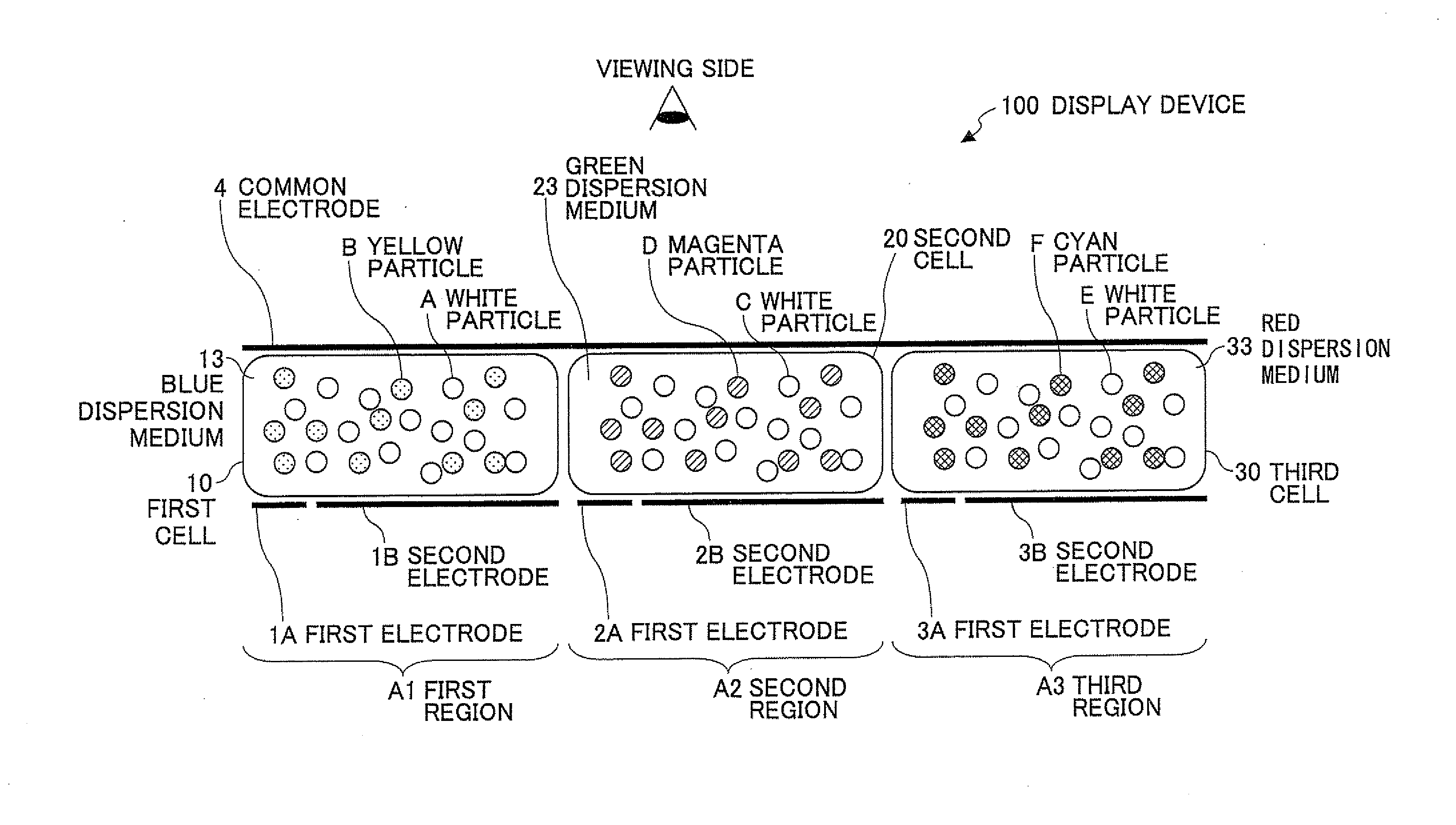
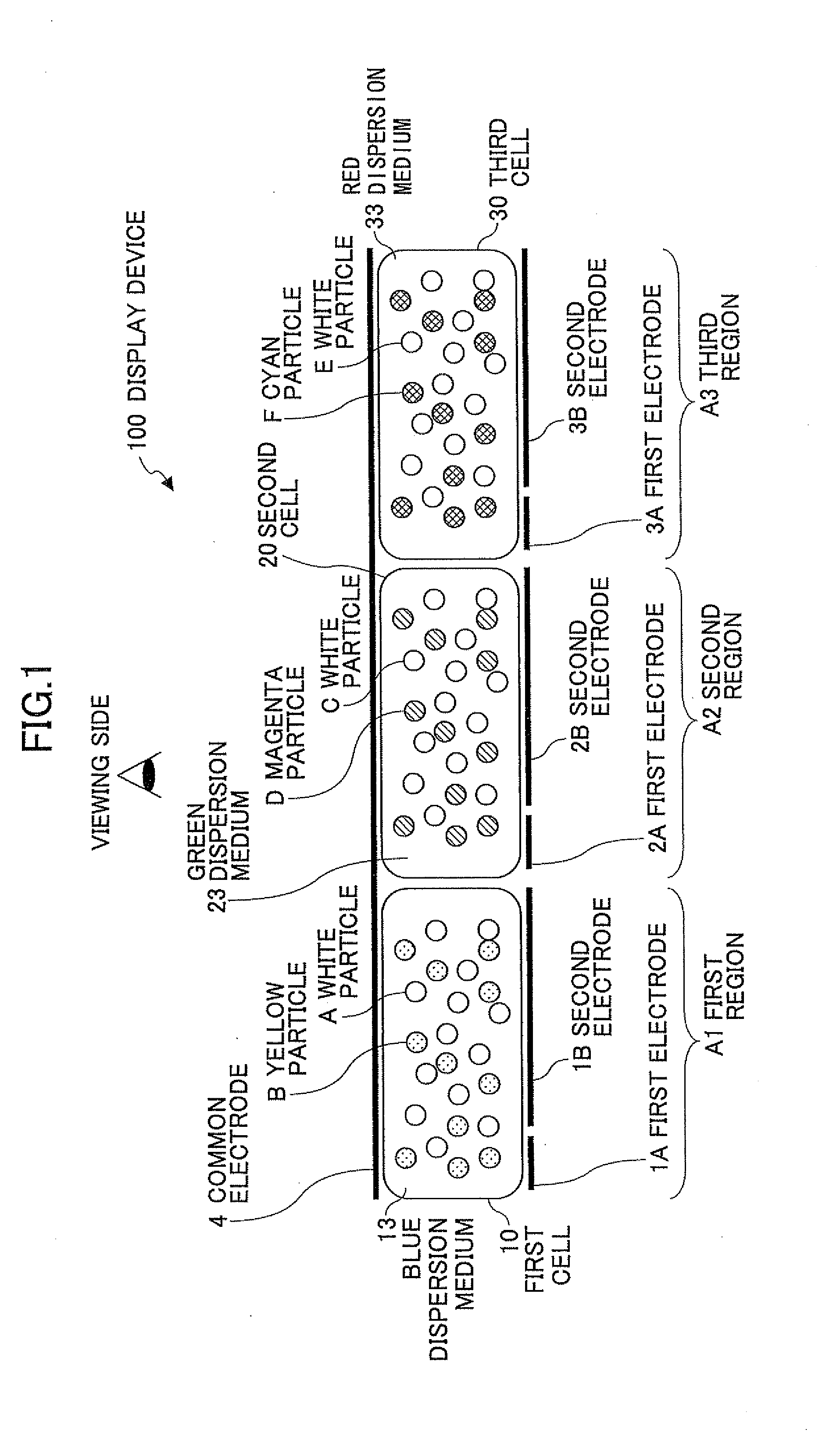
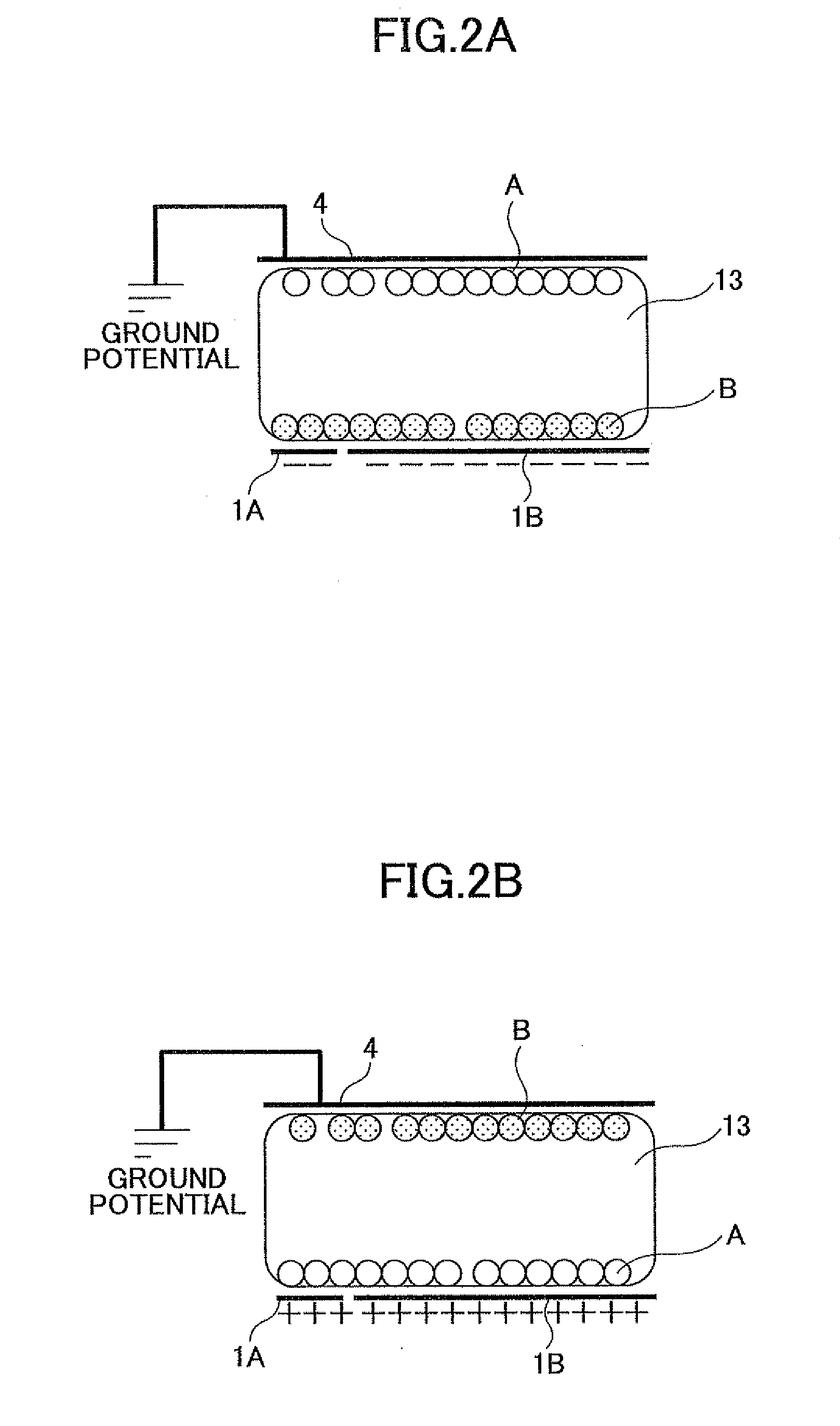
The positively-charged yellow particles and the negatively-charged white particles produced in the above manner were dispersed in the blue dispersion medium 13 as isoparaffinic hydrocarbon (whose product name was “Isopar G” produced by Exxon Mobil corporation) colored in blue obtained by dissolving “Oil Blue N” produced by Sigma-Aldrich Corporation. Note that in the dispersion liquid, the proportion of the positively-charged yellow particles was 5% by weight, the proportion of the negatively-charged white particles was 30% by weight, and “Solsperse 17000” was added as a surfactant.

example 2

Production of the Electrophoretic Liquid 2 Used in the Second Region A2 (the Second Cell 20))

The positively-charged magenta particles and the negatively-charged white particles produced in the above manner were dispersed in the green dispersion medium 23 as “Isopar G” colored in green obtained by dissolving “Solvent Green 3” produced by Sigma-Aldrich Corporation. Note that in the dispersion liquid, the proportion of the positively-charged magenta particles was 5% by weight, the proportion of the negatively-charged white particles was 30% by weight, and “Solsperse 17000” was added as a surfactant.

example 3

Production of the Electrophoretic Liquid 3 Used in the Third Region A3 (the Third Cell 30)

The positively-charged cyan particles and the negatively-charged white particles produced in the above manner were dispersed in the red dispersion medium 33 as “Isopar G” colored in red obtained by dissolving “Sudan Red 7B” and “Oil Red 5B” produced by Sigma-Aldrich Corporation. Note that in the dispersion liquid, the proportion of the positively-charged cyan particles was 5% by weight, the proportion of the negatively-charged white particles was 30% by weight, and “Solsperse 17000” was added as a surfactant.


PUM

PropertyMeasurementUnit
wavelengthaaaaaaaaaa

Abstract

An electrophoretic liquid is disclosed that includes first particles that have the property of scattering light over an entire visible range and are positively or negatively charged; second particles that have the property of absorbing light of a specific wavelength range in the visible range and scattering light of ranges other than the specific wavelength range and are charged to a polarity opposite to that of the first particles; and a dispersion medium that has the property of allowing the light of the specific wavelength range absorbed by the second particles to pass through and absorbing the light of the ranges other than the specific wavelength range. In the electrophoretic liquid, the first particles and the second particles are dispersed in the dispersion medium.

Description

TECHNICAL FIELDThe present invention relates to electrophoretic liquids and display devices such as electronic dictionaries, electronic books, price tags, rewritable message boards, and publicity posters each using the electrophoretic liquids, and, in particular, to a reflective display device suitable for displaying color document information.BACKGROUND ARTAs terminals for displaying so-called images such as texts, still images, and moving images, CRTs (cathode-ray tubes) and LCDs (liquid crystal displays) have been widely used.These devices are capable of instantly displaying and rewriting digital data, but it is hard for users to carry these devices with them at all times. In addition, since these devices are self-luminous, users get eye strain after a prolonged period of operations. Moreover, when these devices are turned off, display of images cannot be maintained. On the other hand, when texts and still images are distributed or stored in the form of a document, they are recor...

Claims


Application Information

Patent Timeline
Patent Type & Authority Applications(United States)
IPC IPC(8): G02F1/167C09K11/06
CPCG02F1/167G02F2203/34G02F2001/1678
Inventor KAWASHIMA, IKUEMASUZAWA, MASAHIROYANAGISAWA, MASAHIRONAIJO, YOSHIHISA
Owner TRANSCEND OPTRONICS (YANGZHOU) CO LTD
Learn More