Microphone

a microphone and microphone technology, applied in the field of microphones, can solve the problems of reducing the degree of freedom of layout, unable to provide the microphone terminal on the rigid substrate, and imposing restrictions on the layout of the mems capacitor inside the housing, so as to reduce the noise resistance, increase the degree of freedom, and the effect of reducing the noise resistan

Inactive Publication Date: 2011-06-09
HOSIDEN CORP
View PDF4 Cites 11 Cited by
  • Summary
  • Abstract
  • Description
  • Claims
  • Application Information

AI Technical Summary

Benefits of technology

This patented describes a miniature loudspeaker (MEM) design used in electronic devices like mobile phones. It includes a flexible base material attached at least once during manufacturing process. A detector circuit is then placed onto another surface without being affected by any physical connections within its interior volume. By placing these parts together instead of just physically attaching them individually, flexibility increases efficiency while reducing costs associated with fabrication processes. Additionally, the use of multiple types of sensors allows for easy customization based on specific needs. Overall, this technology improves sound quality and reduces overall dimensions of the device compared to existing designs.

Problems solved by technology

The technical problem addressed in this patent is the limitation on the layout of the MEMS capacitor in microphones that use the same rigid substrate for mounting both the MEMS capacitor and the IC chip. This limitation can affect the acoustic characteristics of the microphone and lead to higher electrical resistance, reduced noise resistance, and difficulty in achieving mass production cost reduction. The patent aims to provide a solution that allows for greater flexibility in the layout of the MEMS capacitor without compromising its electrical performance.

Method used


Image

  • Microphone
  • Microphone
  • Microphone

Examples


Embodiment Construction

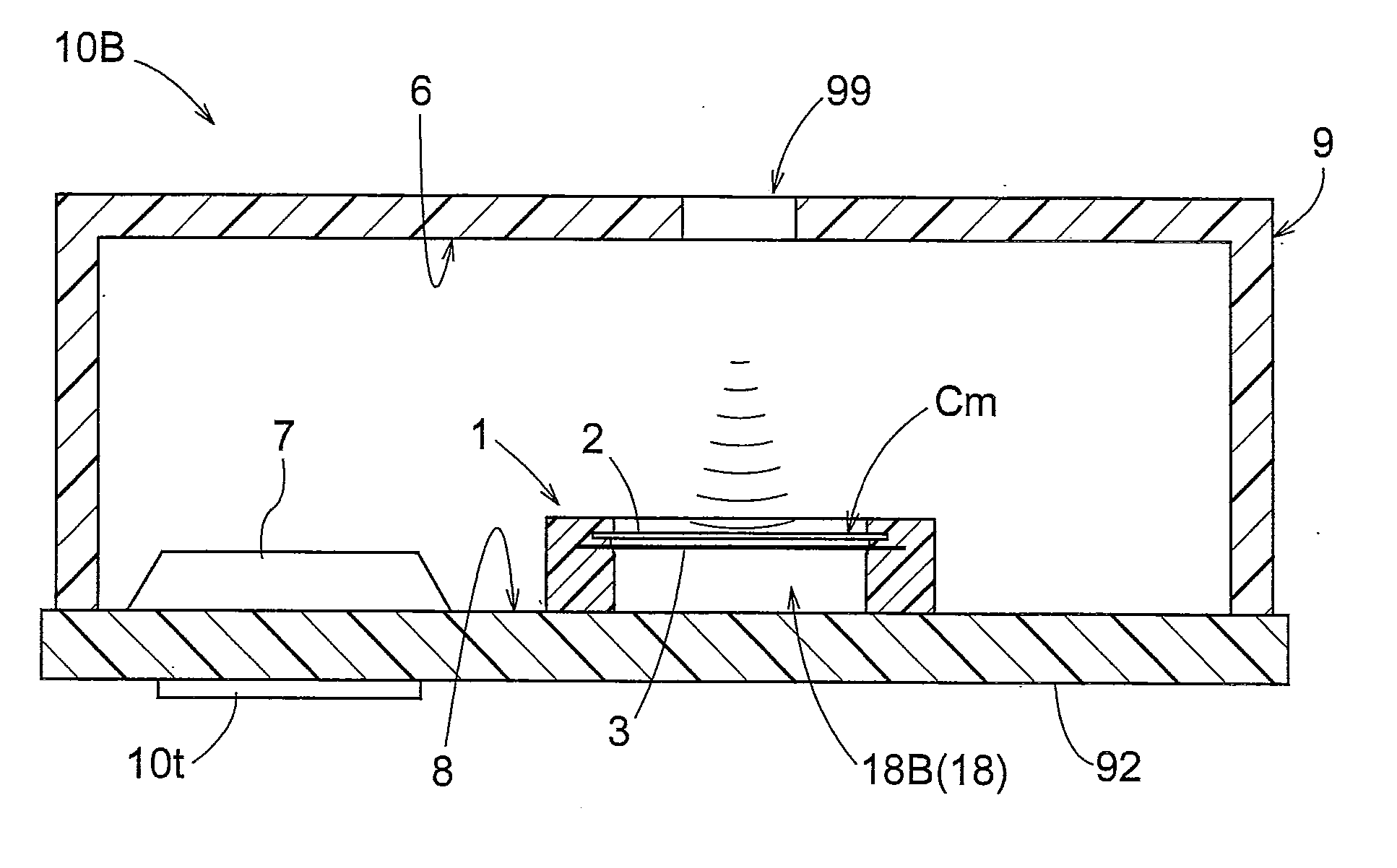
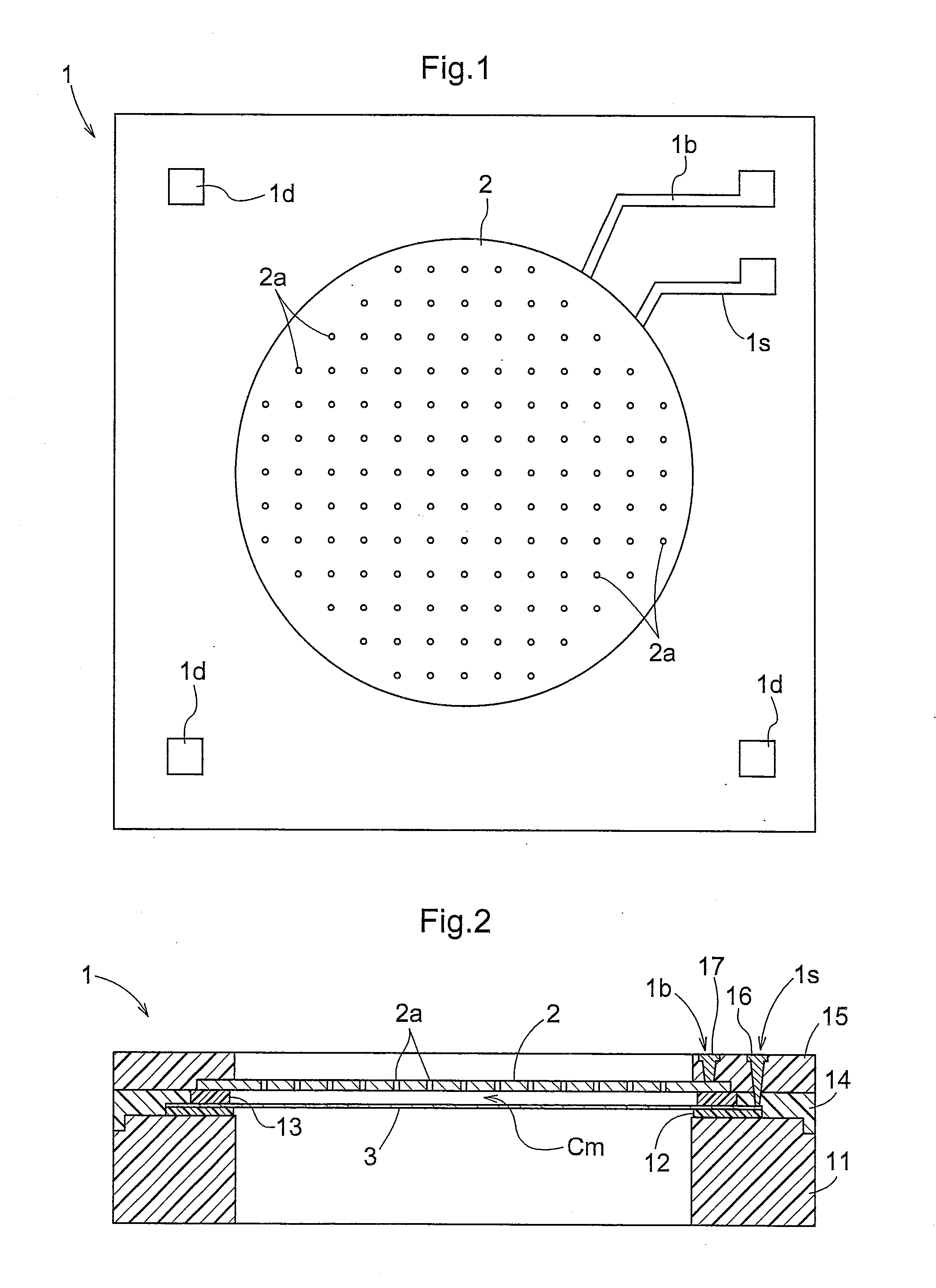
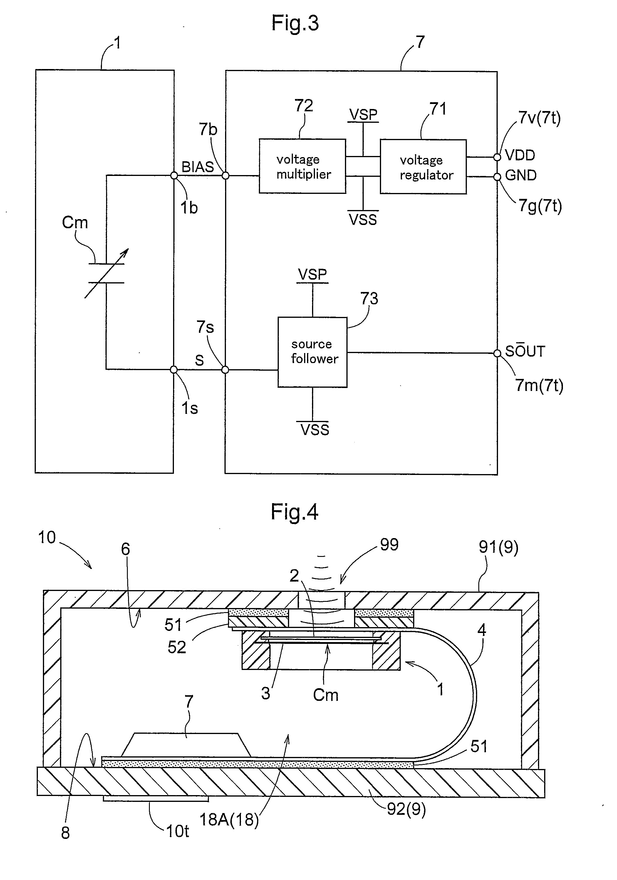
[0029]Next, embodiments of the present invention will be described with reference to the accompanying drawings. An MEMS capacitor 1, as is well-known, is a capacitor manufactured by the MEMS (micro electro mechanical systems) technique, with using a semiconductor processing technique from a monocrystal silicon substrate. As shown in FIG. 1 and FIG. 2, the MEMS capacitor 1 includes a back electrode plate 2 defining many holes 2a, and a diaphragm plate 3 which oscillates in response to a sound. Between the back electrode plate 2 and the diaphragm plate 3, a space is created to form a capacitor Cm. The back electrode plate 2 and the diaphragm plate 3 are formed of electrically conductive material. The back electrode plate 2 is connected to an electrode 17 which forms a terminal 1b on the outer surface of the MEMS capacitor 1. Further, the diaphragm plate 3 is connected to an electrode 16 which forms a terminal is on the outer surface of the MEMS capacitor 1. Between a silicon substrate...


PUM


Abstract

A microphone has a housing (9) defining an acoustic hole (99) and having inner faces. The microphone includes a MEMS capacitor (1) secured to and electrically connected with a first face (6) of the inner faces of the housing (9), the first face defining the acoustic hole (99), a detecting circuit (7) secured to and electrically connected with a second face (8) of the inner faces of the housing (9), the second face (8) being not adjacent the first face (6), the detecting circuit (7) detecting at least a change in the electrostatic capacity of the MEMS capacitor (1). The microphone further includes a flexible substrate (4) secured to the first face (6) and the second face (8) and disposed under a bent state inside the housing (9). The flexible substrate (4) establishes electrical connection between the MEMS capacitor (1) and the detecting circuit (7) via a wire electrically connecting the first face (6) and the second face (8).

Description


Claims


Application Information

Patent Timeline
Owner HOSIDEN CORP
Why Eureka
Try Eureka