Wind turbine rotor blade

Active Publication Date: 2011-06-09
GENERAL ELECTRIC CO
View PDF19 Cites 7 Cited by
  • Summary
  • Abstract
  • Description
  • Claims
  • Application Information

AI Technical Summary

Benefits of technology

[0009]As described herein, the exemplary embodiments overcome one or more of the above or other disadvantages known in the art.
[0010]One aspect of the exemplary embodiments relates to a rotor blade for a wind turbine. A rotor blade for a wind tu

Problems solved by technology

One difficult aspect of the design of the blade connection to the rotor hub is the load transfer from the fiber composite structure of the rotor blade to the metal structure of the rotor hub.
Such a load transfer is difficult in principle due to the substantially different properties of the materials involved.

Method used


Image

  • Wind turbine rotor blade
  • Wind turbine rotor blade
  • Wind turbine rotor blade

Examples


Embodiment Construction

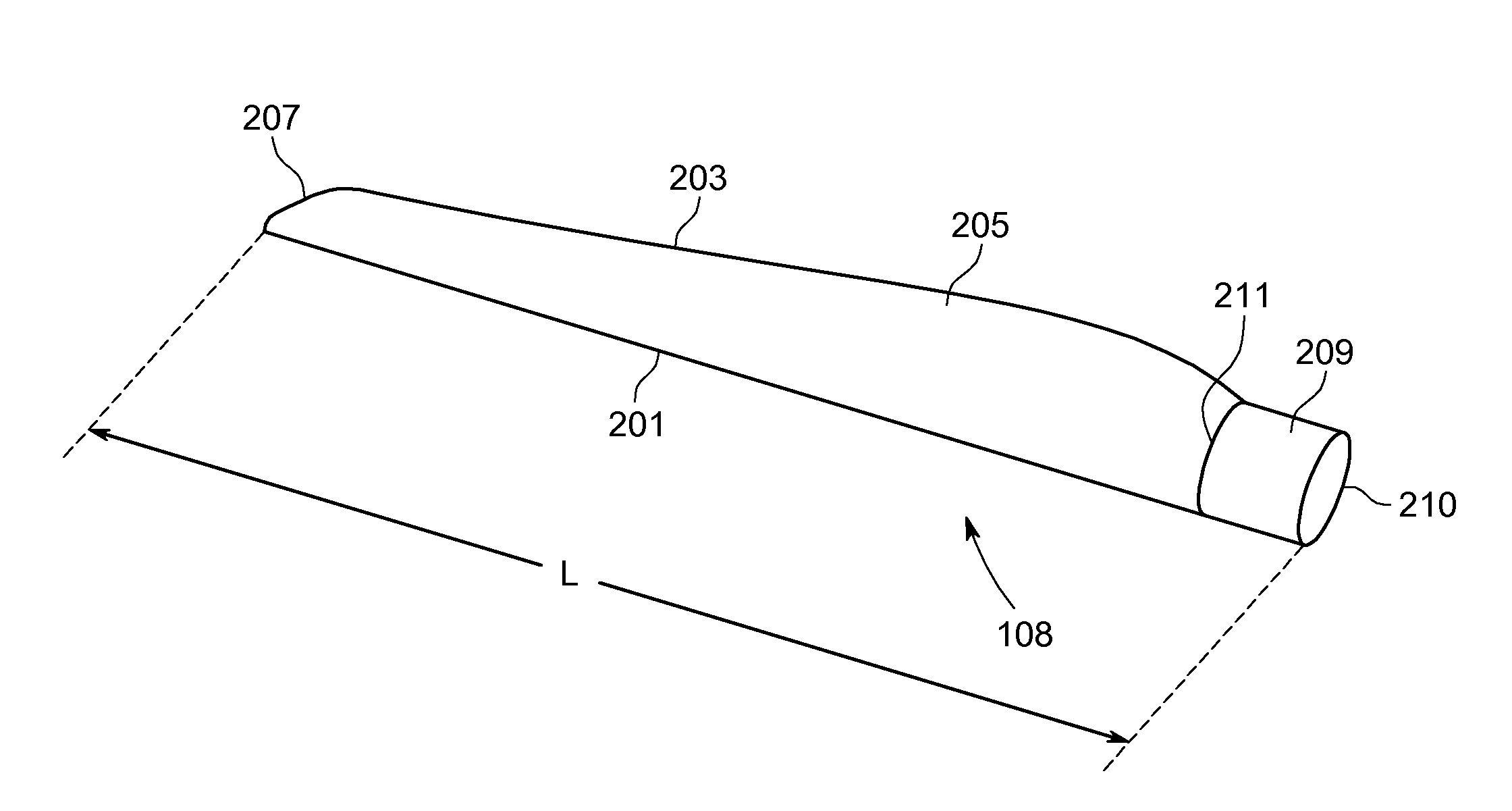
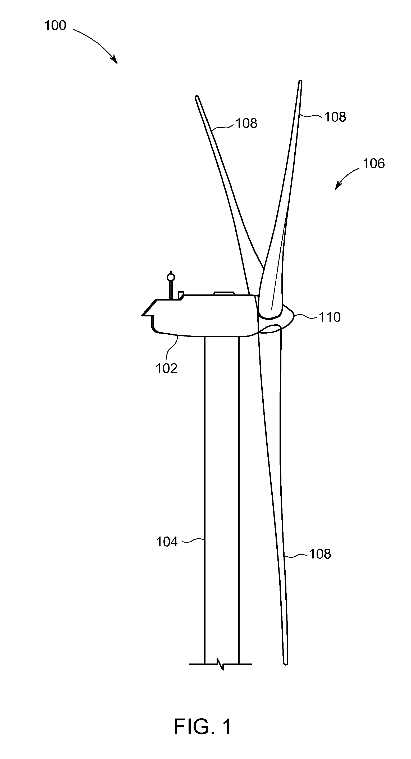
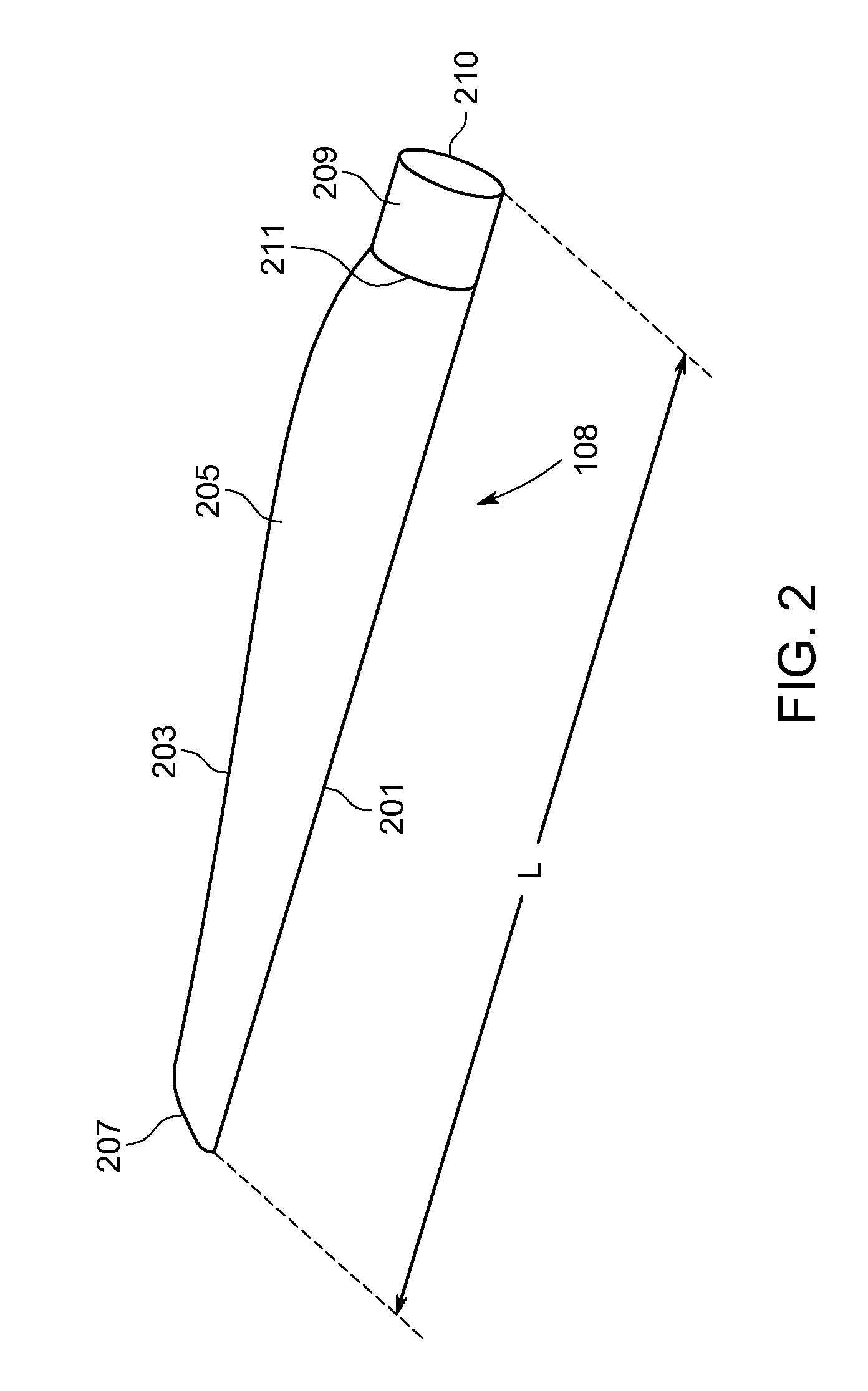
[0021]FIG. 1 illustrates an exemplary wind turbine 100 incorporating aspects of the disclosed embodiments. The aspects of the disclosed embodiments are generally directed to providing a flange section or blade root for a rotor blade, which blade root incorporates a carbon reinforced polymer, thereby allowing for reductions in a size of the blade root diameter and the number of joint bolts compared to conventional blade roots.

[0022]As shown in FIG. 1, the wind turbine 100 includes a nacelle 102 and a rotor 106. Nacelle 102 is a housing that is mounted atop a tower 104. The nacelle 102 includes a generator (not shown) disposed therewithin. The height of the tower 104 is selected based upon factors and conditions known in the art, and may extend to heights up to 60 meters or more. The wind turbine 100 may be installed on any terrain providing access to areas having desirable wind conditions. The terrain may vary greatly and may include, but is not limited to, mountainous terrain or off...


PUM


Abstract

A rotor blade for a wind turbine is disclosed. The rotor blade includes a flange section configured to connect the rotor blade to a rotor hub; and an airfoil section extending outward from the flange section. The flange section is comprised of a carbon reinforced polymer.

Description

BACKGROUND OF THE INVENTION[0001]The present disclosure generally relates to wind turbines, and, more particularly, to a flange section for connecting a rotor blade to a hub of a wind turbine.[0002]Wind turbines have received increased attention as an environmentally safe and relatively inexpensive alternative energy source. With this growing interest, considerable efforts have been made to develop wind turbines that are reliable and efficient.[0003]Generally, a wind turbine includes a rotor comprised of a hub and a plurality of blades mounted on the hub. The rotor is usually coupled to a generator through a gearbox. The generator is mounted within a housing or nacelle, which is positioned on top of a tubular tower. Utility grade wind turbines (i.e., wind turbines designed to provide electrical power to a utility grid) can have large rotors (e.g., thirty or more meters in diameter). Blades of such a rotor transform wind energy into a rotational torque or force that drives the genera...

Claims


Application Information

Patent Timeline
IPC IPC(8): F01D5/28F01D5/30
CPCY02E10/721F03D1/0658Y02E10/72
Inventor B, ACHUTHANSAMBAMURTY, SARAVAKOTA
Owner GENERAL ELECTRIC CO
Why Eureka
Try Eureka