Multiple wafer cortical bone and cancellous bone allograft with cortical pins

a cancellous bone and multi-layer technology, applied in the field of bone allografts, can solve the problems of cancellous bone or cancellous bone simply collapsing or crushing between the cortical end wafers, and achieve the effects of reducing the stress placed on the allograft, preventing fracturing, and adding stability to the allogra

Inactive Publication Date: 2011-06-09
TRANSPLANT TECH OF TEXAS
View PDF16 Cites 29 Cited by
  • Summary
  • Abstract
  • Description
  • Claims
  • Application Information

AI Technical Summary

Benefits of technology

[0014]The smaller diameter end portions of the cortical pin correspond to and are inserted within the end cortical bone wafers of the allograft. The junctions of the small end portions of the cortical pin with the thick middle diameter of the cortical pin create a shoulder on each side of the thick middle diameter. The shoulders aid in absorbing the brunt of the force asserted on the allograft by a surgical mallet or other appropriate medical device during insertion of the allograft.
[0016]However, if too many cancellous bone wafers are placed adjacent one another such that the width of the adjacent cancellous segments become too wide, or if a single cancellous bone member is created too wide, the cancellous wafer or wafers will simply collapse or crush between the cortical end wafers during insertion of the allograft and / or during remodeling or incorporation of the allograft. It is therefore desirable—especially where larger allografts are required—to have inner cortical bone wafers interspersed between adjacent cancellous bone wafers to add structural integrity and additional load-bearing support to the inner portion of the allograft to prevent such crushing.
[0018]In one aspect of the invention, all of the wafers are disposed side by side such that sides of the wafers which are adjacent one another are substantially flat. However, in another aspect of the present invention, the wafers comprise a trough and shelf, or tab and groove configuration to interlock adjacent wafers. This incorporated feature serves two purposes. First it aids is absorbing insertion forces associated with surgically placing the allograft. Second, it provides additional strength to the composite allograft to decrease the likelihood of the allograft fracturing during the remodeling process. One of the end cortical wafers has a tab along the side of the cortical wafer that is disposed on the internal side of the allograft. A groove is disposed along the adjacent side of an adjacent cancellous wafer. The groove is formed to snugly receive the tab of the end cortical wafer. On the side of the cancellous wafer opposite the groove is a tab substantially the same as the tab on the end cortical wafer.
[0020]The allograft of the present invention is inserted into the surgically altered area of the patient with its assembled sections laying perpendicular to the way the other allografts in the art are inserted. Specifically, the allograft is inserted such that the cortical pin runs with, or parallel to the plane of insertion as opposed to perpendicular to the plane of insertion. By inserting the allograft parallel to the plane of insertion, one end cortical wafer is receiving the direct impact from the surgical mallet or other insertion device, and the other end cortical wafer is receiving the transferred impact from the cortical pin. Moreover, insertion of the allograft parallel to the plane of insertion aids in preventing fracturing and reducing stress placed on the allograft during the remodeling process.
[0021]The tab and groove configuration of the wafers allows the wafers to interlock with one another to add stability of the allograft during insertion and especially during remodeling. Furthermore, the tab of the end cortical wafer provides an elevated shelf which is adjacent the shoulder formed by the junction of the end portion and the middle diameter of the pin. As the wafer is impacted by the mallet during insertion, the energy is transferred through the allograft by the cortical pin and is absorbed by the end cortical wafer and the end portion of the cortical pin disposed therein.
[0022]Specifically, the configuration of the cortical pin allows the energy from the mallet to be transferred from the thin end portion disposed within the end cortical wafer that receives the direct impact from the surgical mallet to the thick middle diameter of the cortical pin. The energy is then displaced through middle diameter of the bone pin to the tab of the opposite end cortical wafer, where the shoulder formed by the junction of the end portion and middle diameter of the cortical pin abuts the opposite end cortical wafer. Thus, the construction of the cortical pin and the allograft, in addition to the alignment of the allograft in relation to the plane of insertion allow for optimal energy transfer and displacement through the allograft to minimize the risks of the cortical pin breaking and / or the allograft otherwise coming apart.

Problems solved by technology

However, if too many cancellous bone wafers are placed adjacent one another such that the width of the adjacent cancellous segments become too wide, or if a single cancellous bone member is created too wide, the cancellous wafer or wafers will simply collapse or crush between the cortical end wafers during insertion of the allograft and / or during remodeling or incorporation of the allograft.

Method used


Image

  • Multiple wafer cortical bone and cancellous bone allograft with cortical pins
  • Multiple wafer cortical bone and cancellous bone allograft with cortical pins
  • Multiple wafer cortical bone and cancellous bone allograft with cortical pins

Examples


Embodiment Construction

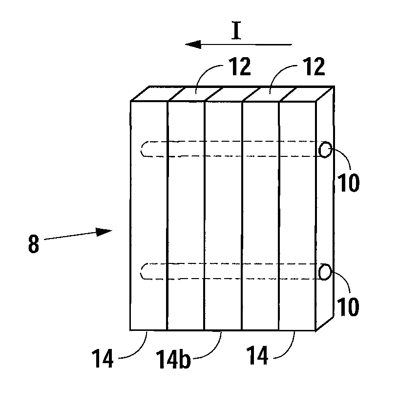
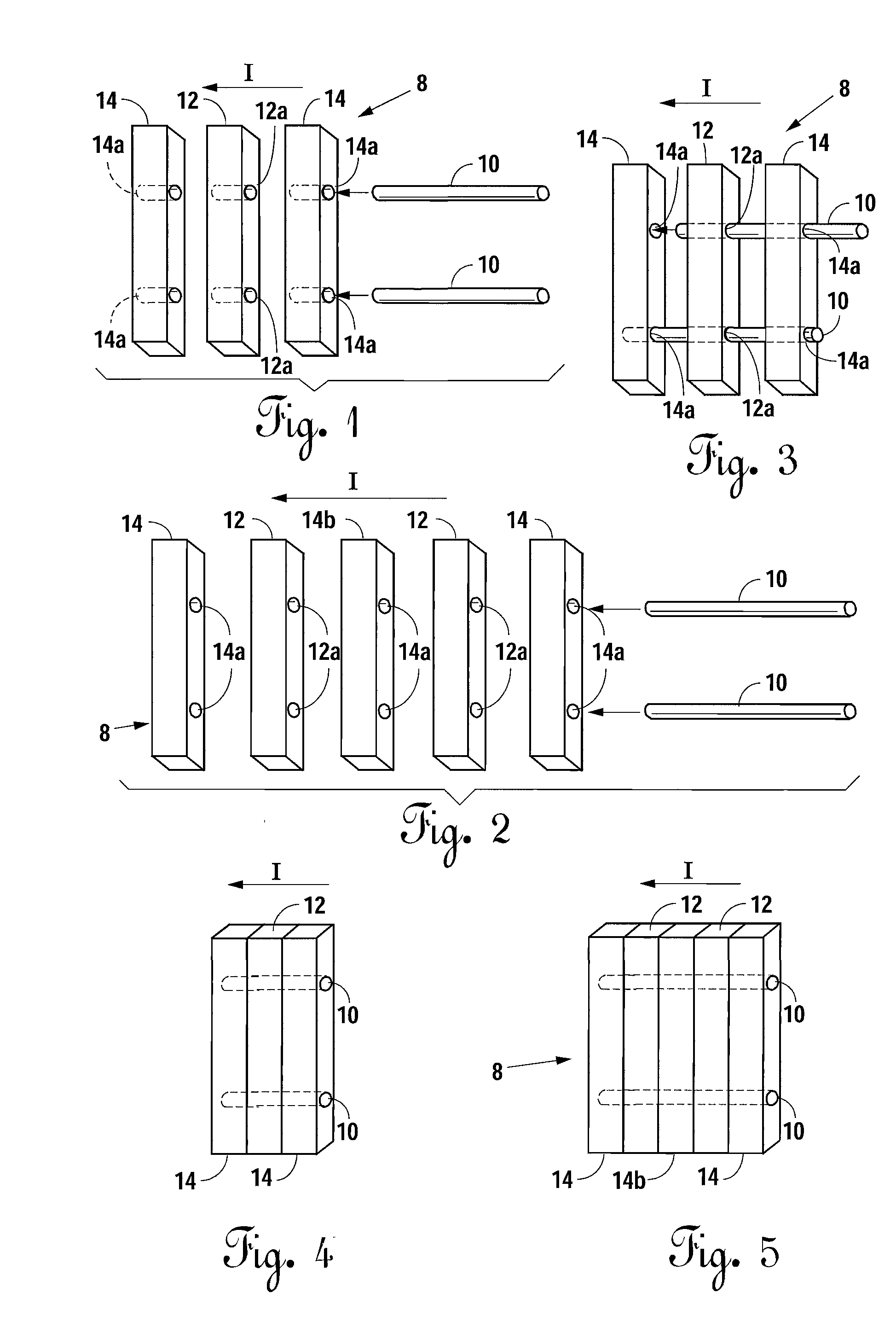
[0039]Referring to FIGS. 1-5, bone allografts 8 of one embodiment of the present invention are disclosed. In FIGS. 1-8 herein reference arrow “I” refers to the plane and direction of insertion of the allograft 8 of the present invention into the surgically altered site of the human (not shown). Referring to FIGS. 1, 3 and 4, an embodiment depicting a three-wafer allograft 8 is disclosed. The three-wafer allograft 8 has two end wafers 14. Wafers 14 are cortical bone wafers. A cancellous bone wafer 12 is disposed adjacently between cortical wafers 14.

[0040]Each cortical wafer 14 and cancellous wafer 12 has at least one canal 14a and 12a, respectively. The canals 14a and 12a are all substantially aligned with one another such that cortical pin 10 is inserted through the canals 14a and 12a of the cortical wafers 14 and cancellous wafers 12, respectively, to form the allograft 8. Cortical pin 10 is preferably made of cortical bone, and is constructed of a single piece of cortical bone. H...


PUM


Abstract

A bone allograft and cortical pin for inserting into a surgically altered site of a human. The cortical pin is cylindrically shaped and has a thick middle diameter surrounded by two smaller end portions. The allograft has two end cortical wafers with small canals to receive the small ends of the cortical pin. At least one cancellous wafer is disposed adjacently between the end cortical bone wafers. A plurality of cancellous and / or cortical wafers may be inserted between the end cortical wafers to form the allograft. The wafers inserted between the end cortical wafers have larger canals to receive the thick diameter of the cortical pin. The size of the allograft may be adjusted as desired by either adding or removing inner wafers, or adjusting the size of the inner wafers of the allograft. The allograft and cortical pin are inserted parallel to the plane of insertion into the human.

Description

BACKGROUND OF THE INVENTION[0001]1. Field of the Invention[0002]The present invention relates to a bone allograft for implantation into a surgically altered area or site of a human, and more specifically, a bone allograft having a plurality of cortical bone and cancellous bone segments or wafers articulating with one another through a series of tabs and notches therein. A cortical pin is inserted through the widths of the respective bone wafers to form the allograft. The cortical pin is substantially cylindrically shaped, having thin diameter along its end portions and a thick middle diameter, thereby creating a shoulder to absorb stress placed on the allograft by insertion into the surgically altered site and to channel the stress throughout the cortical bone rather than the cancellous bone portion of the graft.[0003]2. Description of the Related Art[0004]A common problem many people encounter either as they get older or through injury is the collapsing of inter-vertebral discs. As...

Claims


Application Information

Patent Timeline
Patent Type & Authority Applications(United States)
IPC IPC(8): A61F2/28
CPCA61F2/28A61F2/4455A61F2/447A61F2002/30057A61F2310/00359A61F2002/30383A61F2002/30492A61F2002/30604A61F2002/30607A61F2002/302
Inventor LEE, JOHN W.
Owner TRANSPLANT TECH OF TEXAS
Why Eureka
Try Eureka