Peek Around User Interface

a user interface and user technology, applied in the field of graphical user interfaces, can solve the problems of limiting the ability of operating system shells to render multiple windows, tools, icons, etc. simultaneously, and the physical dimensions of the computer display screen are much more limited

Inactive Publication Date: 2011-06-09
MICROSOFT TECH LICENSING LLC
View PDF23 Cites 47 Cited by
  • Summary
  • Abstract
  • Description
  • Claims
  • Application Information

AI Technical Summary

Benefits of technology

[0006]Windows may be rendered beside each other or may have a top to bottom order in which they are displayed, with top windows at a particular location on the screen overlaying any other window at that same location according to a z-order (an order of the windows along a conceptual z-axis normal to the desktop or display screen). The top-most window has the “focus” and accepts the user's input. The user can switch other windows to the top (and thereby change the z-order) by clicking on the window with a mouse or other pointer device, or by inputting certain key combinations. This allows the user to work with multiple application programs, files and documents in a manner similar to physically working with multiple paper documents and items that can be arbitrarily stacked or arranged on an actual desk.
[0010]In yet another prior implementation referred to as pop-ups / drop-downs, a user interface affordance (e.g., a menu name) is acted on by user to produce an overlay of other elements such as a window full of menu items that are separately selectable. Typically, this overlay is easily dismissed from the display screen. Finally, in still another prior implementation referred to as drawers, a user interface affordance at the edge of a display screen or window can be pulled out to reveal an overlay of objects or menu items, in the manner of a cabinet drawer. Typically the user can control the amount of the drawer that is pulled out to reveal more or fewer of the objects.
[0011]Such prior implementations attempting to compensate for the fixed and limited extent of display screens may be characterized as allowing a user either to move objects onto the fixed display screen area (e.g., as in scrolling or pop-ups / drop-downs or drawers) or moving objects from the display screen or reducing their size (e.g., morphing). As aspect of the present invention is that the fixed and limited extent of display screens may be effectively extended or enlarged by providing different views of an underlying desktop object.
[0012]The present invention provides an operating system shell with an underlying desktop object that is rendered according to different views. The operating system shell renders on a display screen a desktop graphical user interface with windows, tools, icons, etc. that are within a segment of the desktop object that can be observed (i.e., rendered) from one of the views. In illustrated implementations, the desktop object is of an extent that is greater than can be rendered from a single view. Allowing a user to select or access different views of the desktop object effectively provides an extended desktop that overcomes the fixed and limited display capabilities of conventional operating system shells.
[0014]The present invention allows use of a desktop object that is larger than or extended relative a conventional display screen. Changes between the different views, such as making the change from the perpendicular view to the angled view, is akin to taking a “peek” around an obstruction, in this case the edge of a display screen. Accordingly, this use of different image transformation representations to provide different views of a desktop object may sometimes be referred to as a “peek-around” user interface that quickly reveals portions of desktop object that would normally not be seen.

Problems solved by technology

Typically, the physical dimensions of computer display screen are much more limited than the desires of users to have different windows, tools, icons, etc. rendered simultaneously and the ability of operating system shells to do so.
The result is that the limited extent of display screen “real estate” can limit the ability of operating system shells to render multiple windows, tools, icons, etc. simultaneously.

Method used


Image

  • Peek Around User Interface
  • Peek Around User Interface
  • Peek Around User Interface

Examples


Embodiment Construction

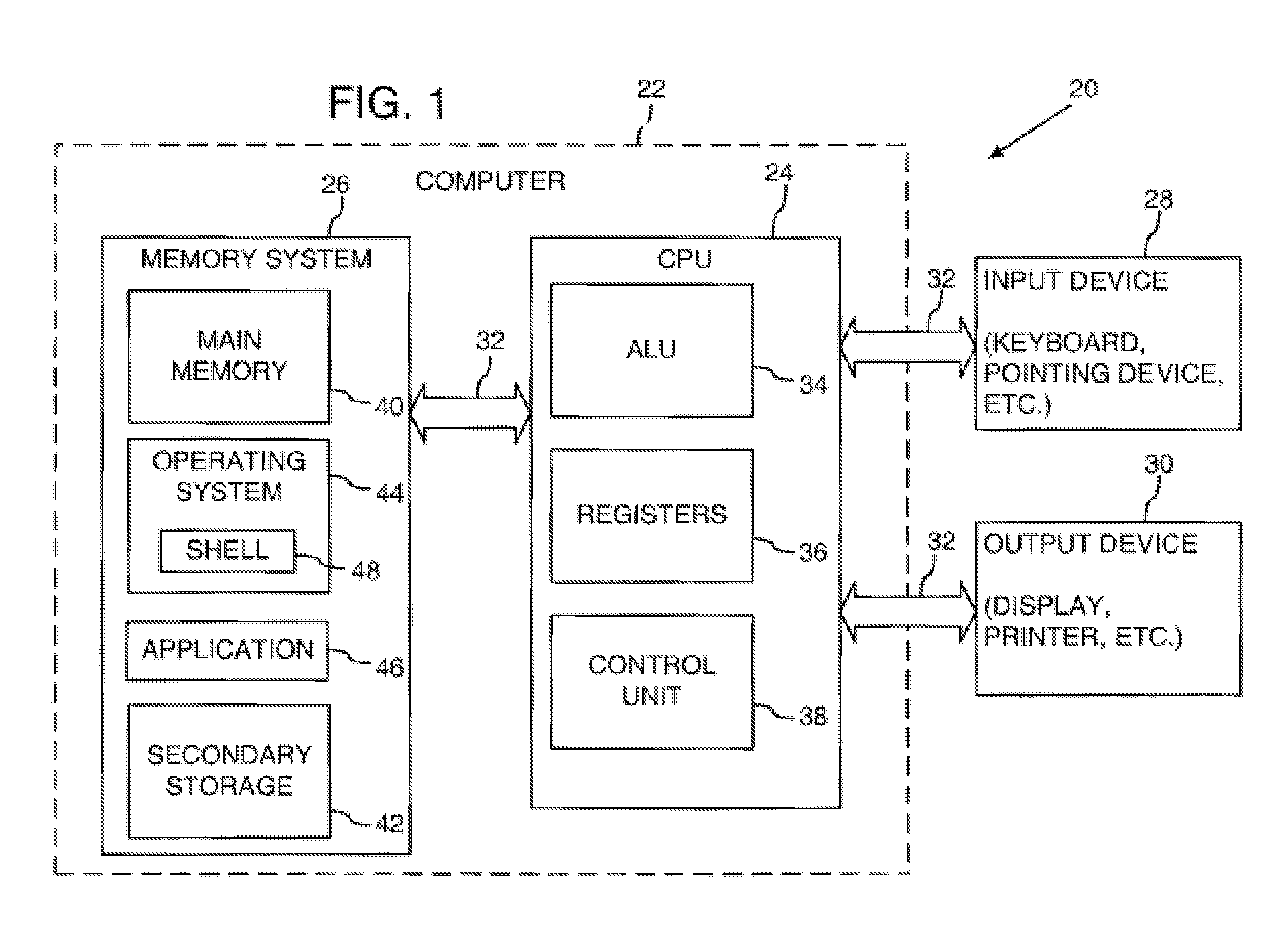
[0025]FIG. 1 illustrates an operating environment for an embodiment of the present invention as a computer system 20 with a computer 22 that comprises at least one high speed processing unit (CPU) 24 in conjunction with a memory system 26, an input device 28, and an output device 30. These elements are interconnected by at least one bus structure 32.

[0026]The illustrated CPU 24 is of familiar design and includes an ALU 34 for performing computations, a collection of registers 36 for temporary storage of data and instructions, and a control unit 38 for controlling operation of the system 20. The CPU 24 may be a processor having any of a variety of architectures including Alpha from Digital, MIPS from MIPS Technology, NEC, IDT, Siemens, and others, x86 from Intel and others, including Cyrix, AMD, and Nexgen, and the PowerPC from IBM and Motorola.

[0027]The memory system 26 generally includes high-speed main memory 40 in the form of a medium such as random access memory (RAM) and read o...


PUM


Abstract

An operating system shell has an underlying desktop object that is rendered according to different views. The operating system shell renders on a display screen a desktop graphical user interface with windows, tools, icons, etc. that are within a segment of the desktop object that can be observed (i.e., rendered) from one of the views. In illustrated implementations, the desktop object is of an extent that is greater than can be rendered from a single view. Allowing a user to select or access different views of the desktop object effectively provides an extended desktop that overcomes the fixed and limited display capabilities of conventional operating system shells.

Description

RELATED APPLICATION[0001]This application is a continuation of U.S. patent application Ser. No. 10 / 112,394, filed on Mar. 29, 2002, which is incorporated by reference herein in its entirety.FIELD OF THE INVENTION[0002]The present invention relates to graphical user interfaces for computer operating systems and, in particular, to a graphical user interface that may be rendered according to different views to provide an enlarged operating system desktop.BACKGROUND AND SUMMARY OF THE INVENTION[0003]It is now common for operating systems to have a shell that provides a graphical user interface (GUI). The shell is a piece of software (either a separate program or component part of the operating system) that provides direct communication between the user and the operating system. The graphical user interface typically provides a graphical icon-oriented and / or menu driven environment for the user to interact with the operating system.[0004]The graphical user interface of many operating sys...

Claims


Application Information

Patent Timeline
Patent Type & Authority Applications(United States)
IPC IPC(8): G06F3/048G06F3/033
CPCG06F3/04815
Inventor VRONAY, DAVID P.CHENG, LILIGUO, BAININGKELLY, SEAN U.
Owner MICROSOFT TECH LICENSING LLC
Why Eureka
Try Eureka