Diesel engine exhaust treatment system

a technology for exhaust treatment and diesel engines, which is applied in the direction of machines/engines, mechanical equipment, surface coverings, etc., can solve the problems of increasing the backpressure in the exhaust system, limited space available for packaging all of these components, and high production costs of the system, so as to achieve compact and efficient removal of undesirable components and minimal backpressure

Active Publication Date: 2011-06-16
FORD GLOBAL TECH LLC
View PDF58 Cites 50 Cited by
  • Summary
  • Abstract
  • Description
  • Claims
  • Application Information

AI Technical Summary

Benefits of technology

[0021]Accordingly, it is a feature of the present invention to provide a diesel engine exhaust treatment system and method which is compact and efficient in removing undesirable components and particulates from the exhaust gas stream with minimal backpressure. Other features and advantages of the invention will be apparent from the following description, the accompanying drawings, and the appended claims.

Problems solved by technology

However, while such a system is efficient for meeting current emission regulations, it suffers from a number of drawbacks.
For example, in some vehicle applications, the available space for packaging all of these components is limited.
In addition, the use of large sized diesel particulate filters including a precious metal catalyst coating makes the system expensive to produce due to the high cost of platinum group metals.
While such an integrated system has a smaller volume, it is known that the presence of a DPF generally results in an increase in backpressure in the exhaust system, which adversely affects catalyst performance and fuel economy.
However, such an increased catalyst loading results in an increase in backpressure and lower fuel efficiency.

Method used


Image

  • Diesel engine exhaust treatment system
  • Diesel engine exhaust treatment system
  • Diesel engine exhaust treatment system

Examples


example 1

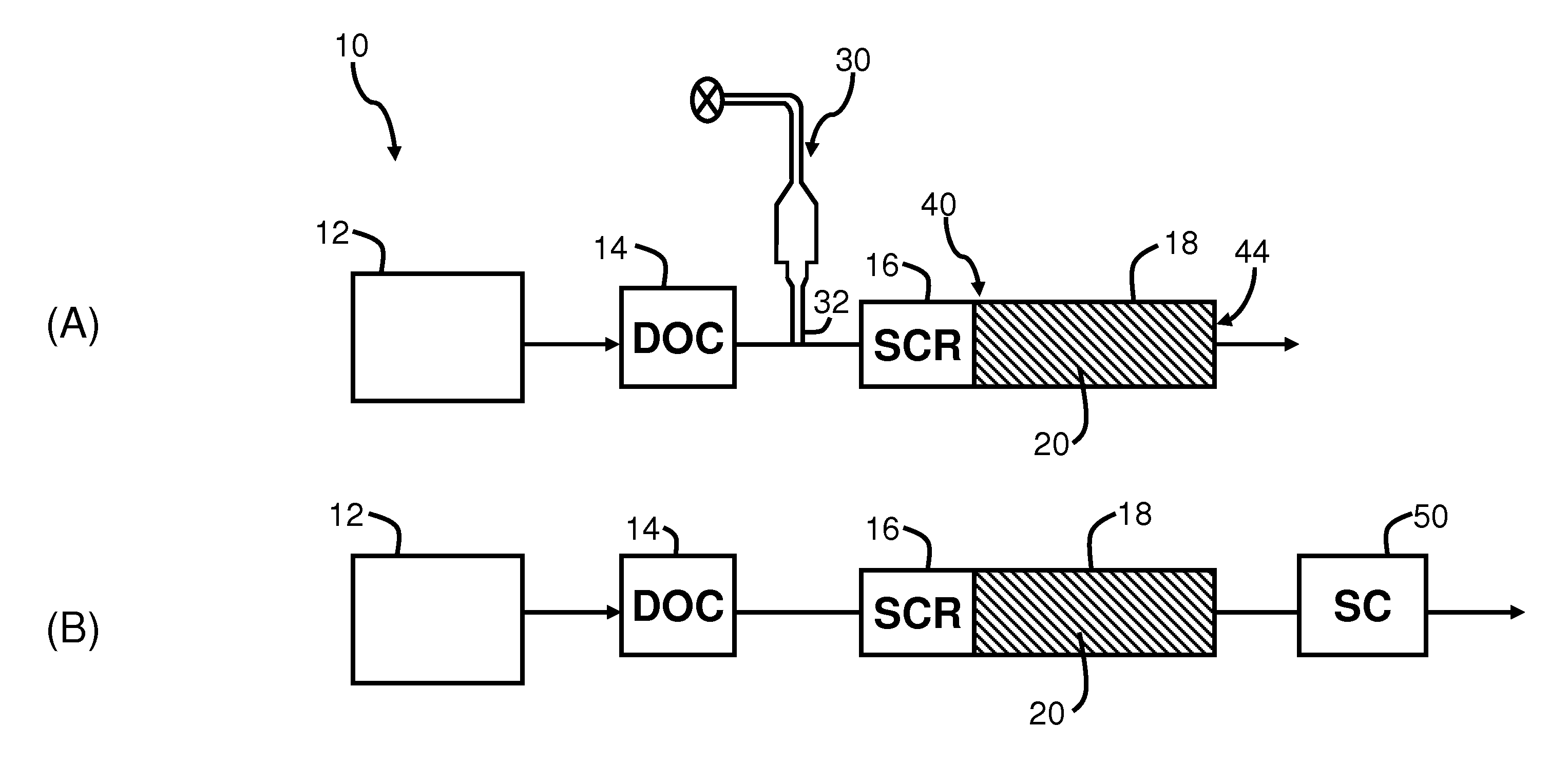
[0046]A conventional SCR catalyst was positioned upstream from an SCR-coated filter having a low washcoat loading of 1.1 g / in3 in accordance with the invention. The system backpressure and conversion efficiencies of the exhaust gas treatment system was compared with a system including a single SCR-coated filter at a higher washcoat loading of 2.1 g / in3.

[0047]The steady state backpressure was measured at a bench flow reactor. The gas flow included 5% CO2, 4.5% H2O and the balance N2, and the total flow rate was 16.1 liter / min. The backpressure measurement was carried out at 150° C. As shown in FIG. 3, the use of a single SCR-coated filter with a loading of 2.1 g / in3 (SCRF_H, 1 “Dx3”L) generated significantly higher backpressure than a bare high porosity (HP) filter substrate. In contrast, an SCR-coated filter with a catalyst loading of 1.1 g / in3 (SCRF_L, 1 “Dx3”L) generated significantly lower backpressure than the first, higher loaded SCR filter (SCRF_H) and only slightly higher bac...

example 2

[0048]The catalytic efficiency of the system of Example 1 was evaluated. Steady state activity testing was conducted under the following conditions: flowing 350 ppm NH3, 350 ppm NOx, 14% O2, 5% CO2, 4.5% H2O, and the balance N2. The total flow rate was 12.88 liter / min. The results are shown in FIG. 4. As can be seen, at the lower catalyst loading used in embodiments of the invention, the single, low-loaded SCR catalyst (SCRF_L) has a lower NOx removal efficiency at the temperature range of 150° C. to 500° C. in comparison with the single, higher loaded SCR-coated filter (SCRF_H). The combined system including a conventional SCR catalyst and low-loaded SCR filter (SCR+SCRF_L) having an equivalent total catalyst loading to SCRF_H showed slightly higher NOx removal than SCR_H alone. It can be seen that an exhaust aftertreatment system including an SCR filter at low loading in combination with a conventional SCR catalyst generates significantly lower backpressure than single catalyst sy...


PUM


Abstract

A diesel engine exhaust treatment system is provided which includes a diesel oxidation catalyst and a diesel particulate filter, where a first SCR catalyst is positioned at the inlet of the diesel particulate filter, and a second SCR catalyst is coated on the filter. The first and second SCR catalysts each have a low loading, such that a lower backpressure is achieved over the use of a single SCR-coated diesel particulate filter at higher catalyst loadings. The exhaust treatment system also provides effective catalyst efficiency for removal of NOx and other gaseous emissions.

Description

BACKGROUND OF THE INVENTION[0001]Embodiments described herein relate to a diesel engine exhaust treatment system, and more particularly, to an exhaust treatment system which utilizes a selective reduction catalyst (SCR) in combination with an SCR-coated diesel particulate filter, where the system achieves reduced backpressure in comparison with a system which utilizes a single SCR-coated filter.[0002]In recent years, environmental regulations in the United States and Europe restricting diesel particulate emissions have necessitated improvements in the removal of particulates from diesel engine emissions. Diesel engine exhaust contains gaseous emissions such as carbon monoxide (CO), unburned hydrocarbons (HC), and nitrogen oxides (NOx), as well as particulate matter.[0003]Diesel engine exhaust treatment systems are currently used to convert these exhaust components to environmentally acceptable compounds and to remove particulates. Such systems typically include the use of a diesel o...

Claims


Application Information

Patent Timeline
Patent Type & Authority Applications(United States)
IPC IPC(8): F01N3/00F01N3/035F01N3/10
CPCF01N3/035F01N3/103F01N3/2066F01N2510/063F01N13/009F01N2610/02Y02T10/24F01N13/0097F01N13/0093F01N2510/0682Y02T10/12
Inventor HUANG, YINYANBADILLO, EDLAMBERT, CHRISTINE KAY
Owner FORD GLOBAL TECH LLC
Why Eureka
Try Eureka