Resonator System for Turbine Engines

a turbine engine and resonator technology, applied in the field of turbine engines, can solve the problems of unoptimized cooling, damage to components acoustic pressure oscillations at undesirable frequencies can develop in the combustor section,

Active Publication Date: 2011-06-16
SIEMENS ENERGY INC
View PDF17 Cites 71 Cited by
  • Summary
  • Abstract
  • Description
  • Claims
  • Application Information

AI Technical Summary

Benefits of technology

[0026]According to the method, the location of a hot region of the fluid flow is determined and a high flow resonator is formed with the combustor component based on the determined location of the hot region such that high flow resonator is substantially aligned with the hot re

Problems solved by technology

During engine operation, acoustic pressure oscillations at undesirable frequencies can develop in the combustor section due to, for example, burning rate fluctuations inside the combustor section.
Such pressure oscillations can damage components in the combustor section.
The placement of resonators based chiefly on acoustic considerations can lead to non-optimized cooling a

Method used


Image

  • Resonator System for Turbine Engines
  • Resonator System for Turbine Engines
  • Resonator System for Turbine Engines

Examples


Embodiment Construction

[0038]Embodiments of the invention are directed to resonator systems adapted to improve their cooling effectiveness and / or acoustic performance. Aspects of the invention will be explained in connection with various resonator configurations, but the detailed description is intended only as exemplary. Embodiments of the invention are shown in FIGS. 2-10, but the present invention is not limited to the illustrated structure or application.

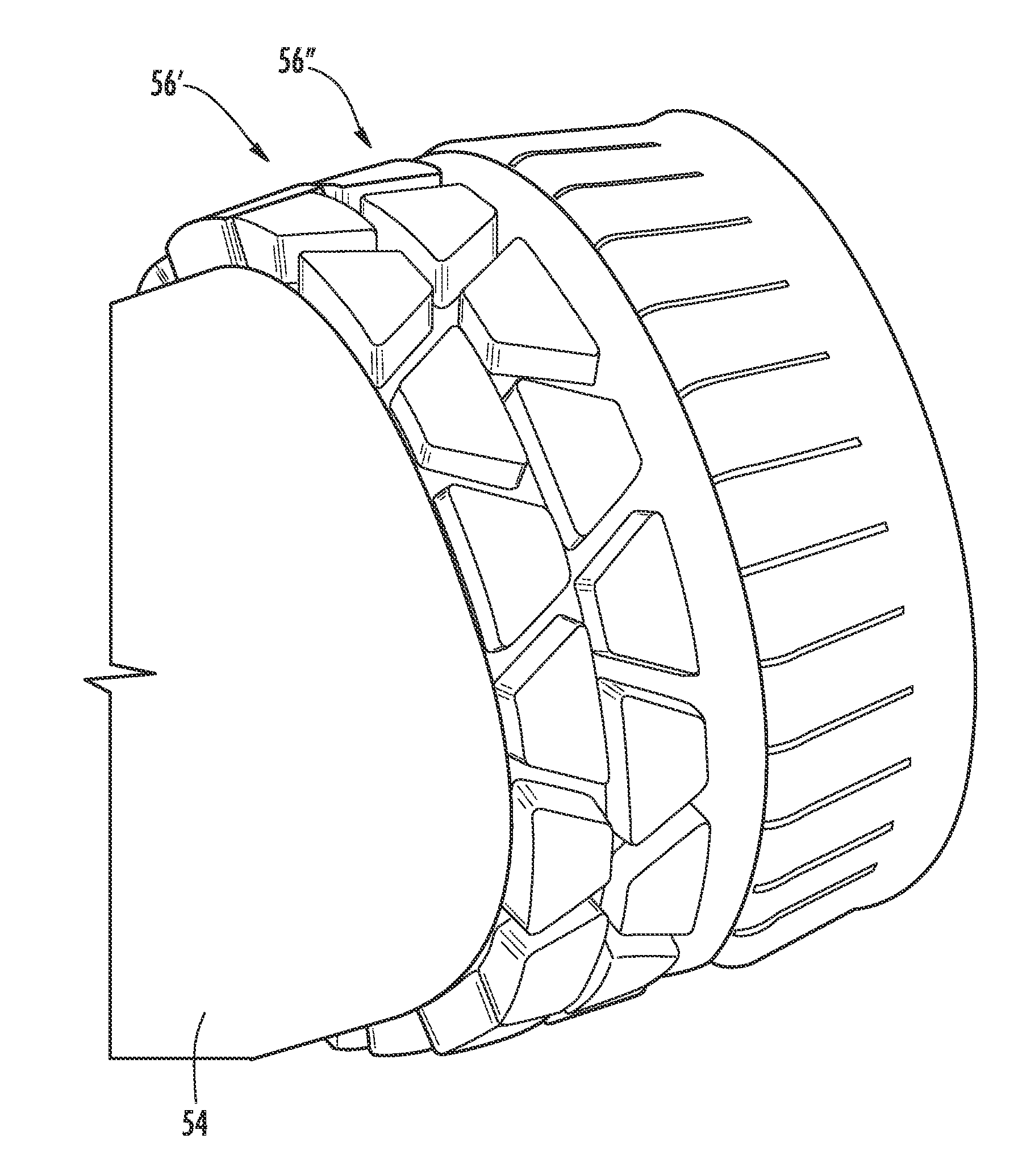
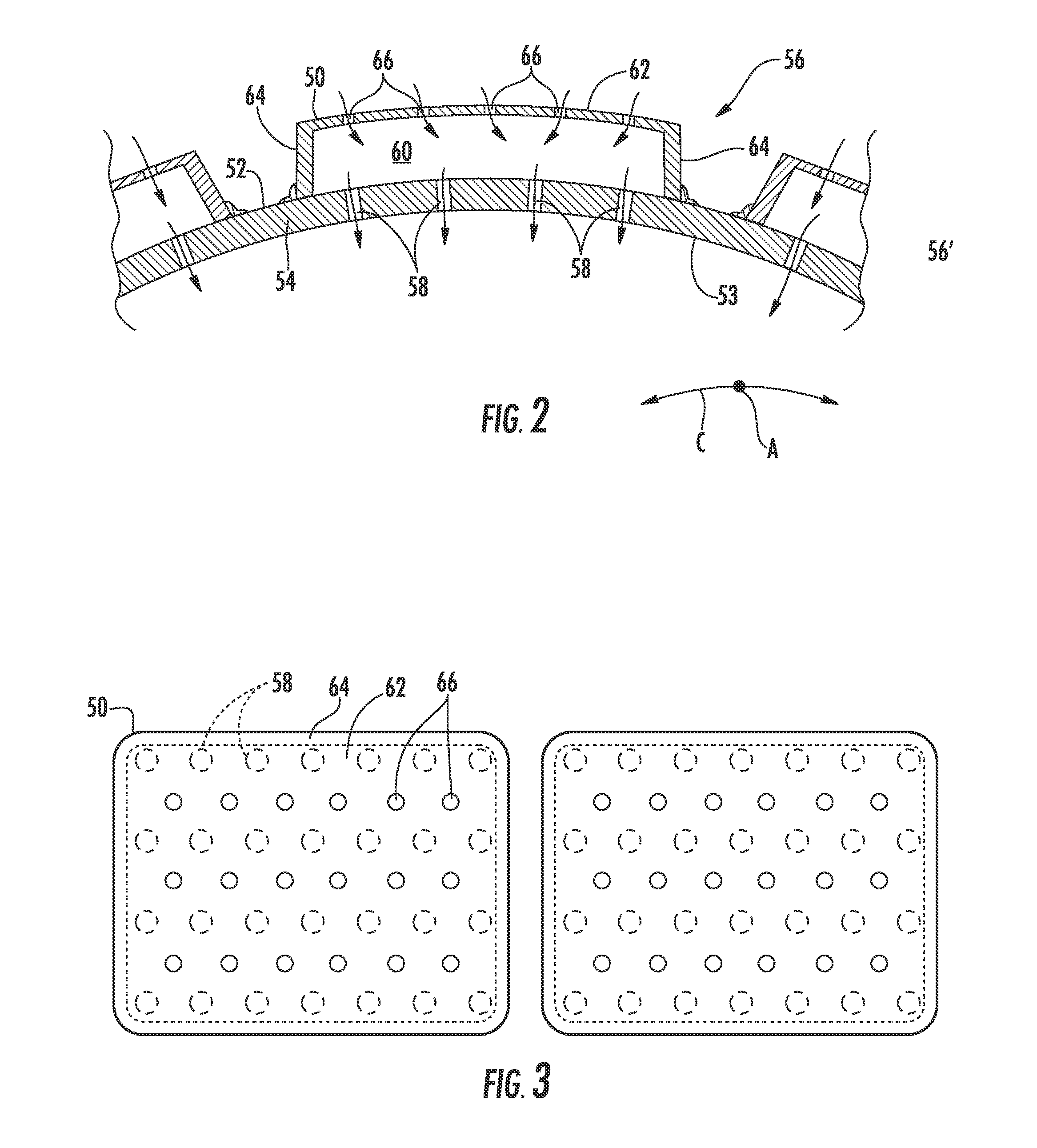
[0039]As is shown in FIG. 2, one or more damping devices can be formed with a surface of a combustor component. For example, a plurality of resonators 50 can be formed with an outer peripheral surface 52 of a combustor component, such as a liner 54 or a transition duct, to thereby form a plurality of resonators 56. The liner 54 can also have an inner peripheral surface 53. The liner 54 can be substantially cylindrical in conformation. The liner 54 can have an associated axial direction A and circumferential direction C relative to the direction of flu...


PUM


Abstract

A resonator system for a turbine engine can improve acoustic performance and cooling effectiveness. During engine operation, a combustor liner exhibits alternating hot and cold regions in the circumferential direction corresponding to the non-uniform temperature distribution of the combustion flame. Accordingly, high flow resonators are formed with the liner in substantial alignment with the hot regions of the fluid flow within the liner, and low flow resonators are formed with the liner in substantial alignment with cold regions of the fluid flow within the liner. As a result, appropriate amounts of cooling can be provided to the liner so that cooling air usage is optimized. Alternatively or in addition, the liner can include two or more rows of resonators, which can provide an enhanced acoustic damping response. The resonators in the first row can be aligned with or offset from the resonators in the second row.

Description

FIELD OF THE INVENTION[0001]The invention generally relates to turbine engines, and more particularly to the use of resonators in turbine engines.BACKGROUND OF THE INVENTION[0002]A turbine engine has a compressor section, a combustor section and a turbine section. In operation, the compressor section can induct ambient air and compress it. The compressed air can enter the combustor section and can be distributed to each of the combustors therein. FIG. 1 shows one example of a known combustor 10. The combustor 10 can include a pilot swirler 12 (or more generally, a pilot burner). A plurality of main swirlers 14 can be arranged circumferentially about the pilot swirler 12. Fuel is supplied to the pilot swirler 12 and separately to the plurality of main swirlers 14 by fuel supply nozzles (not shown). When the compressed air 16 enters the combustor 10, it is mixed with fuel in the pilot swirler 12 as well as in the surrounding main swirlers 14. Combustion of the air-fuel mixture occurs ...

Claims


Application Information

Patent Timeline
IPC IPC(8): F02C7/24
CPCF23R3/00F23M20/005F23R2900/00014
Inventor JOHNSON, CLIFFORD E.
Owner SIEMENS ENERGY INC
Why Eureka
Try Eureka