
Method and Device for Controlling Process Gases for Heat Treatments of Metallic Materials/Workpieces in Industrial Furnaces

a technology of process gases and heat treatment equipment, which is applied in the direction of heat treatment equipment, furnaces, lighting and heating equipment, etc., can solve the problems of disadvantageously high gas loss, no longer usable, and actual gas loss

Active Publication Date: 2011-06-16
IPSEN INT
View PDF3 Cites 6 Cited by
  • Summary
  • Abstract
  • Description
  • Claims
  • Application Information

AI Technical Summary

Benefits of technology

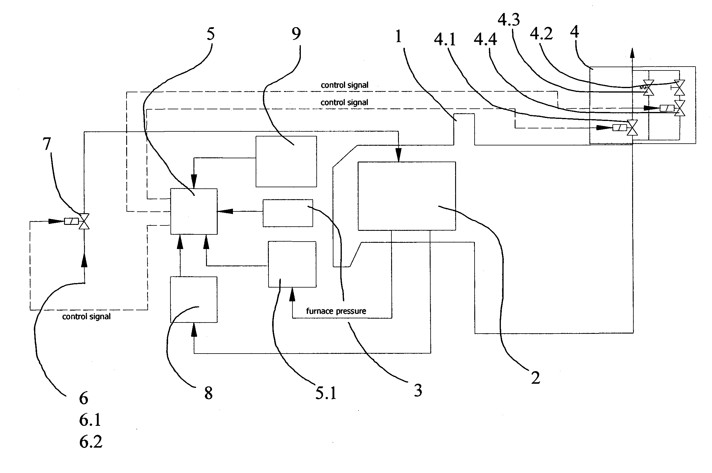
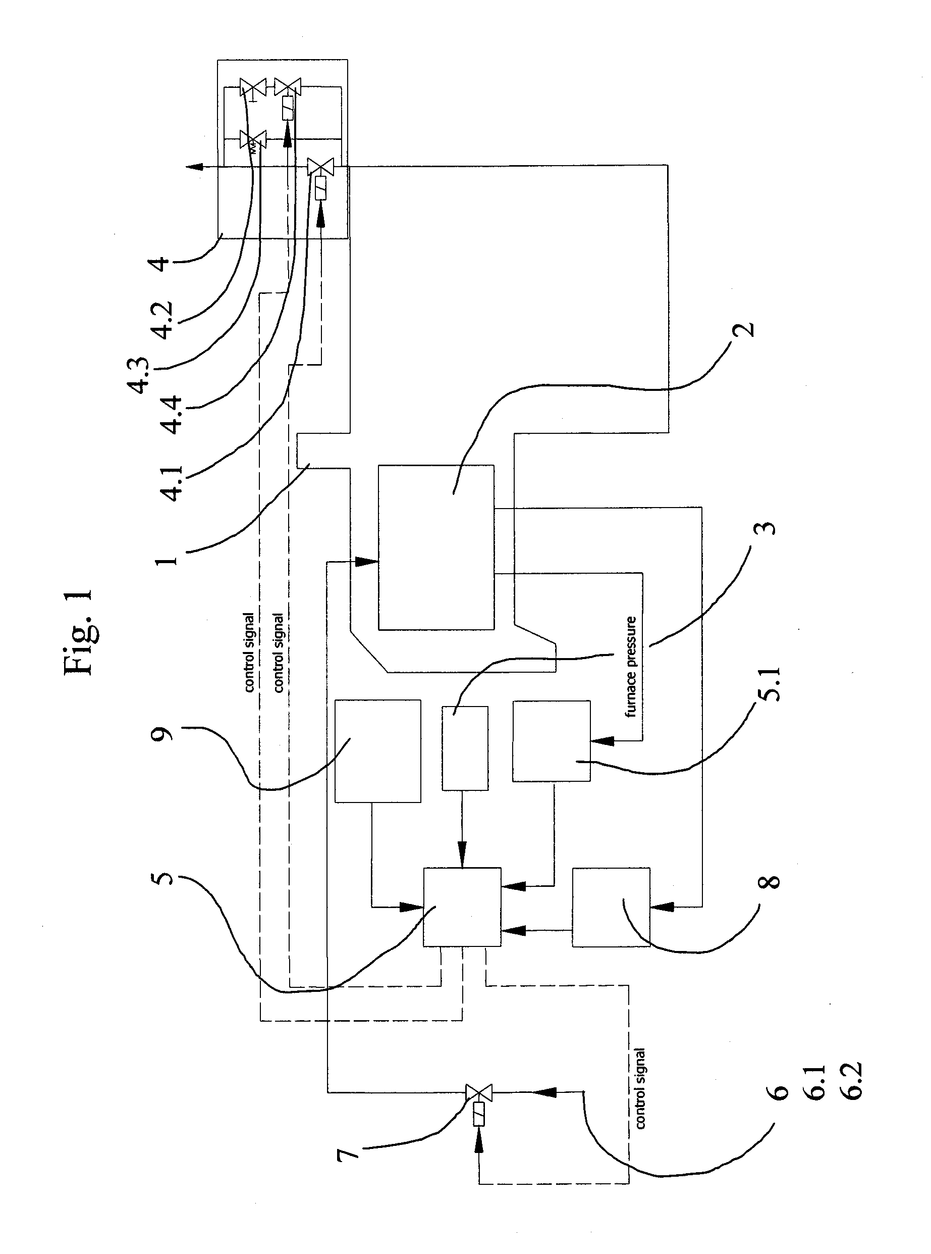
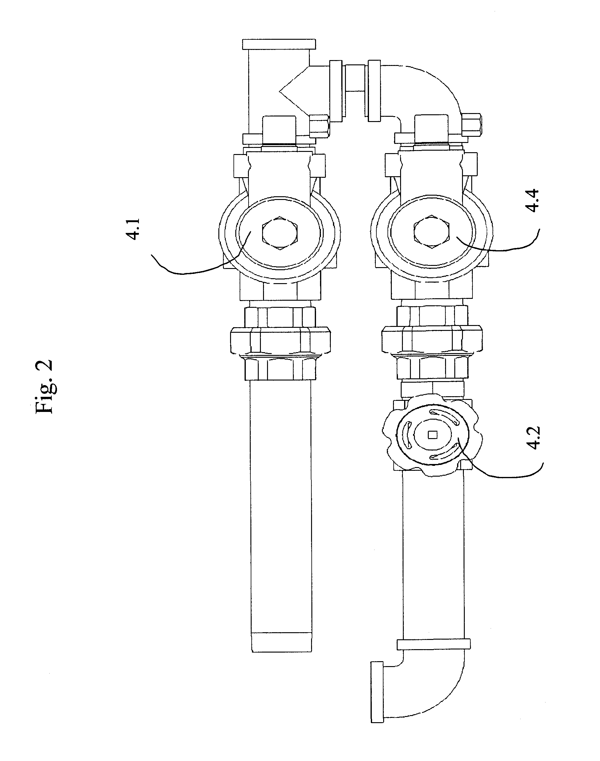
[0045]The device comprises solenoid valves or adjustable valves as valves, which are activated depending on the processing state in the furnace and release the flow through the burnoff point. Various gas quantities may thus be burned off in various burnoff trains. As a function of the program step, furnace pressure, and the atmospheric composition, different valves are activated and only the minimal required quantity of gas is thus burned off. In the case of a disturbance, all valves release the passage and thus allow a rapid flushing out procedure of the furnace chamber. An overpressure flap, which was also typical up to this point, is now implemented according to the invention, however, so that it is regulated closed tight up to an established furnace pressure and is regulated to open upon exceeding this pressure and thus—also essentially regulated—ensures a rapid pressure dissipation.

Problems solved by technology

On the one hand, the thermal loss during flare off of the protective gas at the burnoff and, on the other hand, the actual gas loss, which must be compensated for by new components of the process gas, are disadvantageous in this continuous furnace flushing technique.
In addition, the burnoff gas has a C potential previously defined by the regulator, which is also no longer usable and is simply burned off.
Known burnoff points in this context are functionally characterized by a permanent gas flow and thus by disadvantageously high gas losses according to internally known prior art.

Method used


Image

  • Method and Device for Controlling Process Gases for Heat Treatments of Metallic Materials/Workpieces in Industrial Furnaces
  • Method and Device for Controlling Process Gases for Heat Treatments of Metallic Materials/Workpieces in Industrial Furnaces
  • Method and Device for Controlling Process Gases for Heat Treatments of Metallic Materials/Workpieces in Industrial Furnaces

Examples


Embodiment Construction

[0051]An industrial furnace 1 having a treatment chamber 2 is schematically shown in an exemplary embodiment in FIG. 1. The treatment chamber 2 is connected to a regulator 5 via a pressure meter 5.1, the regulator 5 receiving both request signals for a flushing gasification from a typical furnace controller 9 and also signals from a C potential regulator 3 and the pressure meter 5.1 about the furnace pressure. Furthermore, the regulator 5 receives values from a carbon monoxide analyzer 8.

[0052]The regulator outputs signals for the opening or closing of a burnoff valve 4.1, implemented as a solenoid valve, for example, a burnoff point 4, and signals of a fresh gas valve 7, implemented as a solenoid valve, for example.

[0053]According to the method[0054]in a first step, in terms of a control after a batch change, for example, with open burnoff valve 4.1, a flushing gas quantity 6.1 of a gas mixture is supplied to the industrial furnace 1 and burned off, in order to free the furnace cha...


PUM

PropertyMeasurementUnit
pressureaaaaaaaaaa
pressure meteraaaaaaaaaa
thermal lossaaaaaaaaaa

Abstract

For regulating process gases for heat treatments of metal materials / workpieces in industrial furnaces (1), which have at least one treatment chamber (2), at least one burnoff point (4) having at least one first valve (4.1), and a regulator (5) having pressure meter (5.1), the burnoff point (4) is only to be opened as a function of requirements related to the process gas. For this purpose, in a first step, with open first valve (4.1), a quantity of a flushing gas (6.1) of the gas mixture (6) of the respective process gas is supplied in a controlled manner to the industrial furnace (1) and then burned off, in a second step, the valve (4.1) is closed, the industrial furnace (1) is regulated to a preset furnace pressure and this is permanently detected via the pressure meter (5.1), in a third step, with the target pressure of the industrial furnace achieved, this pressure is detected via the pressure meter (5.1) and maintained, the first valve (4.1) further remaining closed. In a fourth step, the flushing gasification can be activated and adjusted. In the event of large pressure rise, in a fifth step, an overpressure flap (4.3) of the burnoff point (4) can be opened in a controlled manner via a fixed limiting value for pressure dissipation (FIG. 1).

Description

BACKGROUND OF THE INVENTION[0001]1. Field of the Invention[0002]The invention relates to a method and a device for regulating process gases for heat treatments of metal materials / workpieces in industrial furnaces, which have at least one treatment chamber, at least one burnoff point having gastight closable valve, and a pressure regulator, at least one component of the respective process gas being prepared in at least one process-relevant range of dimensions.[0003]2. Description of the Related Art[0004]In general, it is known in industrial furnaces that, for example, in the case of typical carburization gassing, the flushing method is applied. I.e., an established quantity of protective gas is permanently supplied to the furnace continuously and is exhausted from the furnace while being burned off (flared off) at a burnoff point. This flushing is necessary in order to achieve a quasi-stationary equilibrium state in the atmosphere through mixing of continuously newly supplied protect...

Claims


Application Information

Patent Timeline
Patent Type & Authority Applications(United States)
IPC IPC(8): F17D1/16F16K21/04
CPCF27D19/00C21D11/00Y10T137/7837Y10T137/0396
Inventor GROBLER, WERNER HENDRIKEVERSMANN, THOMASEDENHOFER, BERNDBECHTHOLD, JENSJORITZ, DIRKBERNHAGEN, NILS
Owner IPSEN INT
Learn More