

Compressive rod assembly for molten metal containment structure
- Summary
- Abstract
- Description
- Claims
- Application Information
AI Technical Summary
Benefits of technology
Problems solved by technology
Method used
Image

Examples
Embodiment Construction
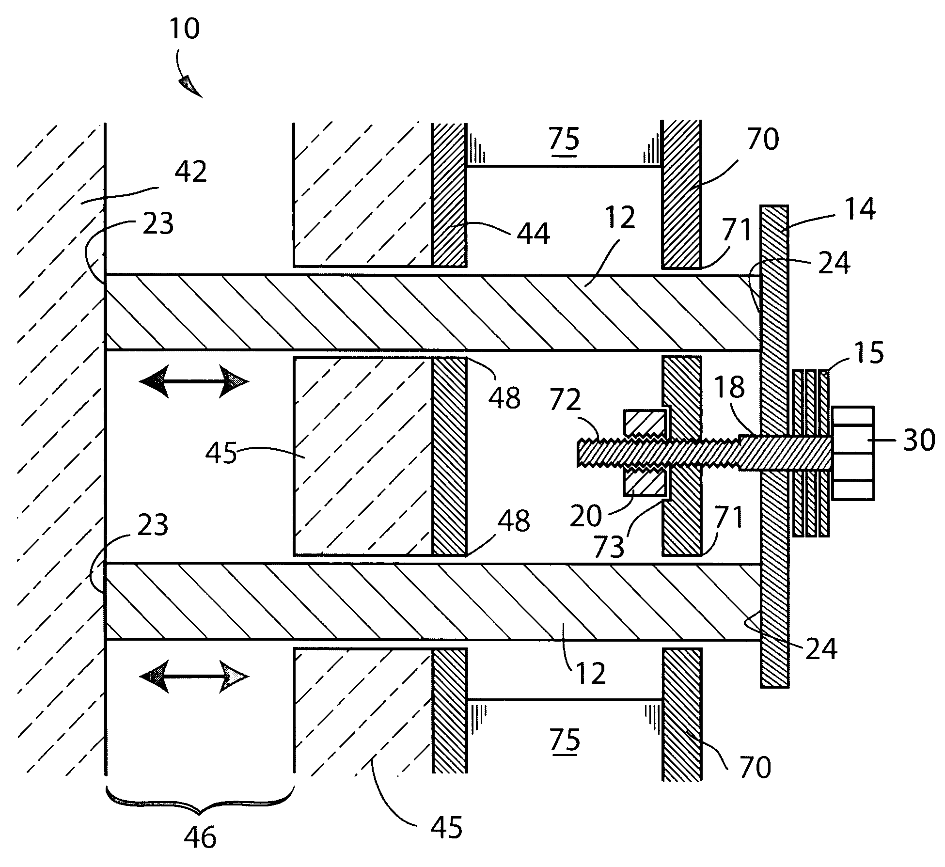
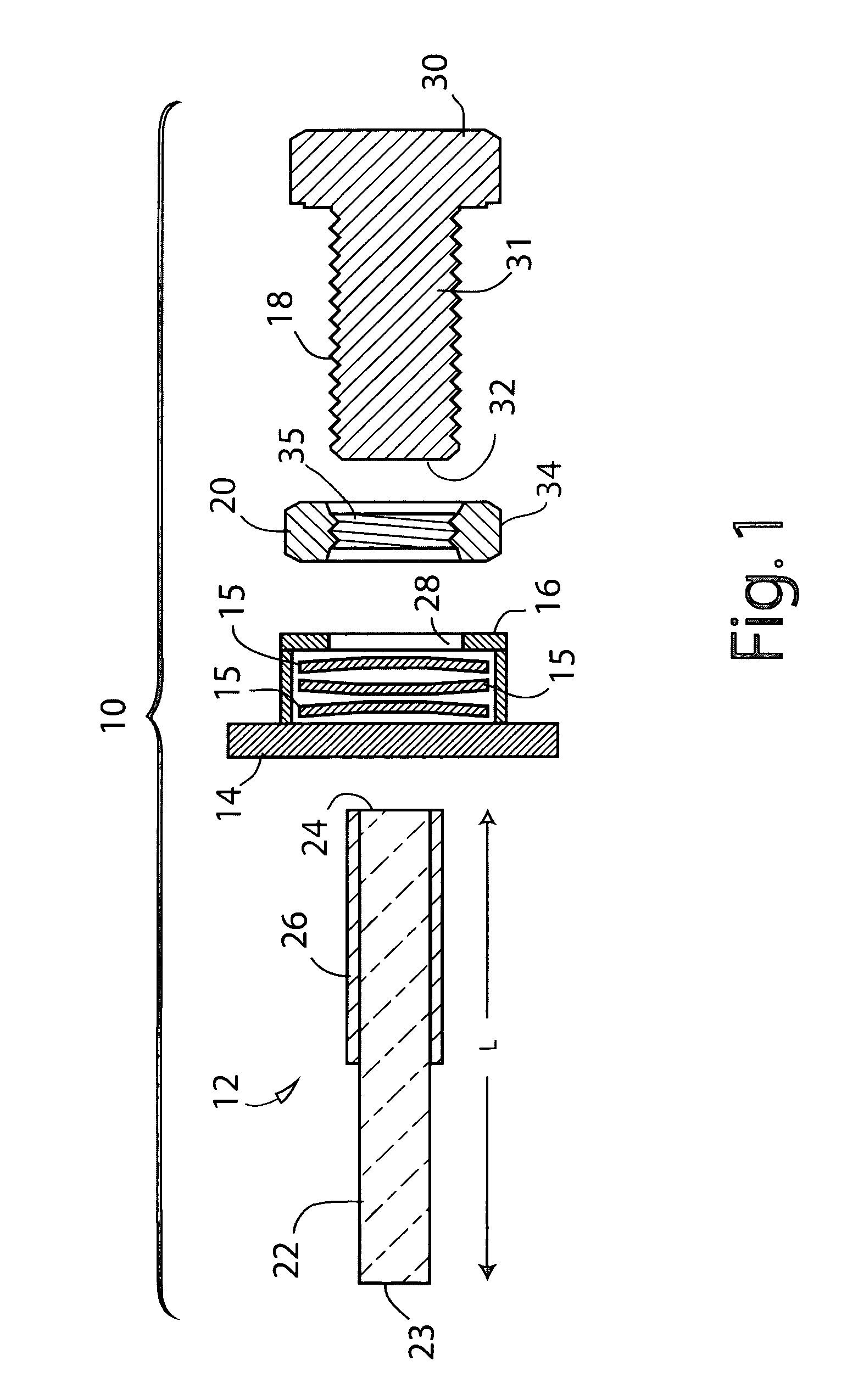
[0008]An exemplary embodiment of the invention provides a compressive rod assembly for applying force to a refractory vessel positioned within an outer metal casing, the assembly comprising a rigid elongated rod having first and second opposed ends, a threaded bolt adjacent to the first opposed end of the elongated rod, and a compressive structure positioned operationally between the elongated rod and the bolt, whereby force applied by the bolt to the elongated rod passes through the compressive structure which allows limited longitudinal movements of the elongated rod to be accommodated by the compressive structure without requiring corresponding longitudinal movements of the bolt.
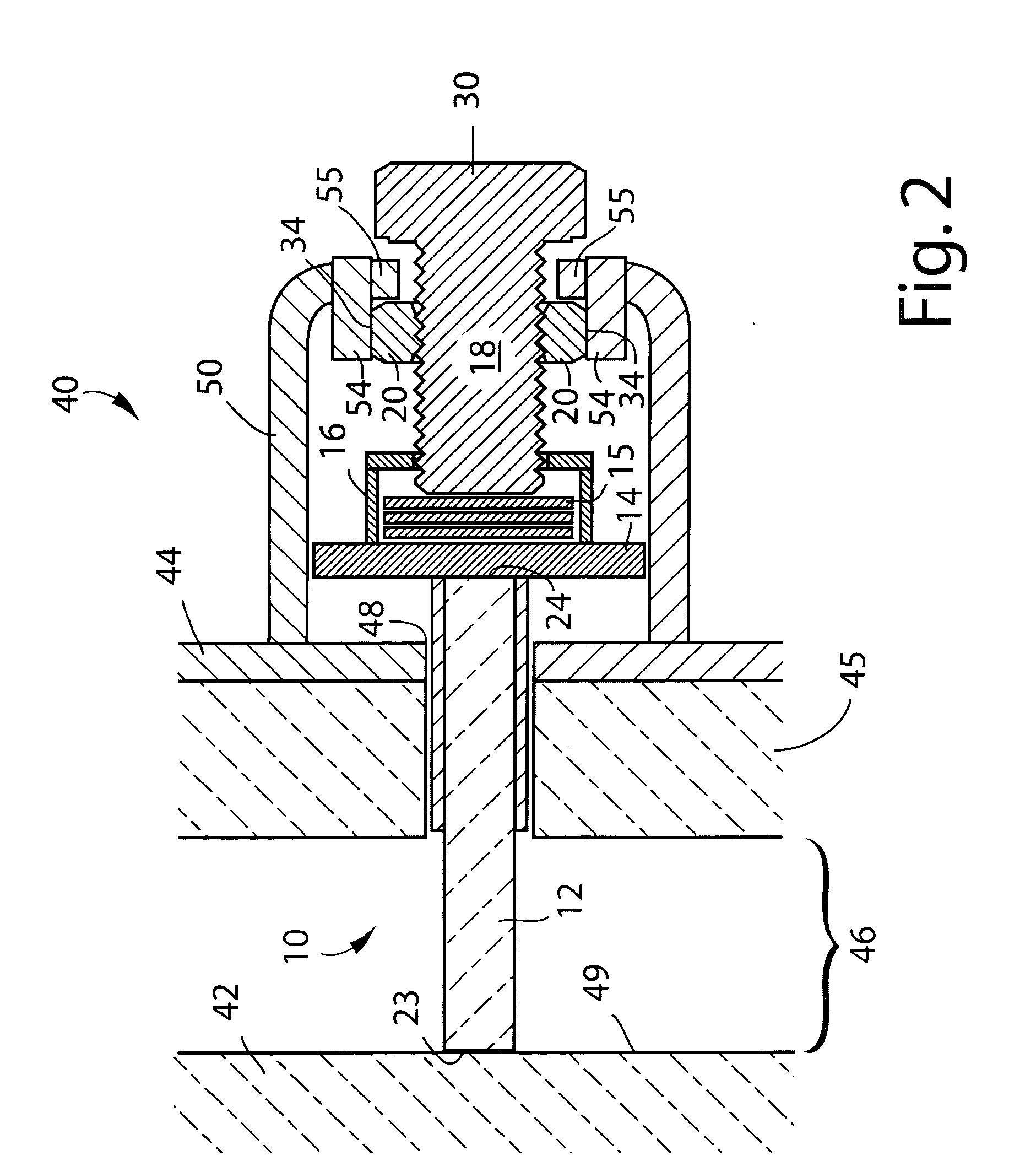
[0009]Another exemplary embodiment provides a molten metal containment structure (e.g. a structure for holding, distributing or conveying molten metal), having a refractory vessel positioned within an outer metal casing, the vessel being spaced from internal surfaces of the casing and being subjected to c...
PUM
| Property | Measurement | Unit |
|---|---|---|
| Mass | aaaaa | aaaaa |
| Distance | aaaaa | aaaaa |
| Distance | aaaaa | aaaaa |
Abstract
Description
Claims
Application Information