Method for operating a hydraulically working brake system, and brake system

a technology of hydraulic brakes and working brakes, applied in the direction of brake safety systems, braking systems, vehicle components, etc., can solve the problems of not being able to build up any pressure in the brake line, and the pump unit needing less electric current, so as to increase the overall safety of the vehicle and prevent pressure loss. affecting the entire hydraulic system

Inactive Publication Date: 2011-06-16
ROBERT BOSCH GMBH
View PDF5 Cites 4 Cited by
  • Summary
  • Abstract
  • Description
  • Claims
  • Application Information

AI Technical Summary

Benefits of technology

[0005]The exemplary embodiments and/or exemplary methods of the present invention provides for the valve to be closed when an unexpected pressure drop in the brake line is detected. The pressure drop is used as a clear indication of damage to the brake line and a subsequent escape of brake fluid. An unexpected pressure drop also refers to the case in which it is not possible to build up any pressure in the brake line. If the pressure unexpectedly drops off sharply, or if it is not possible to build up any pressure, this signifies damage to the brake line, and the valve is closed so that a further escape of brake fluid that

Problems solved by technology

An unexpected pressure drop also refers to the case in which it is not possible to build up

Method used


Image

  • Method for operating a hydraulically working brake system, and brake system
  • Method for operating a hydraulically working brake system, and brake system
  • Method for operating a hydraulically working brake system, and brake system

Examples


Embodiment Construction

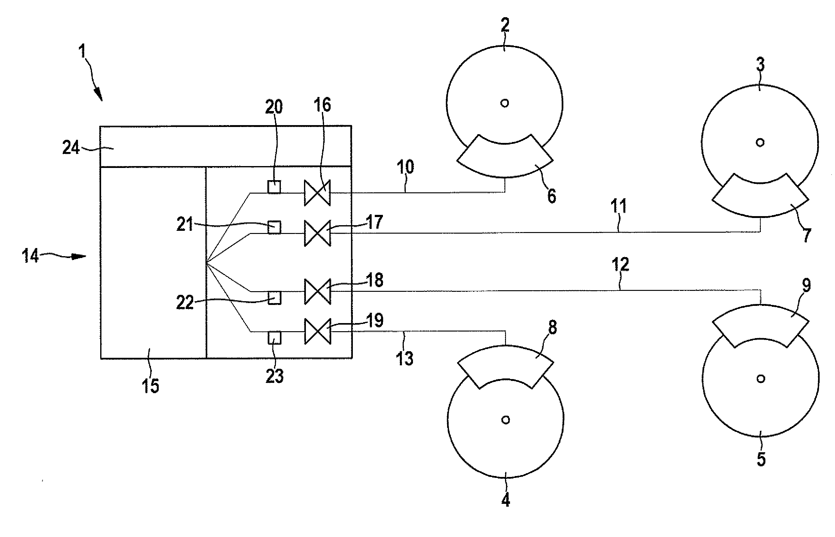
[0018]FIG. 1 shows, in a greatly simplified depiction, a brake system 1 of a motor vehicle (not depicted in further detail here), which has four wheels 2, 3, 4 and 5, to each of which is assigned a wheel brake 6, 7, 8 and 9 of brake system 1. Wheel brakes 6 through 9 are each connected via a brake line 10, 11, 12 and 13 to a braking unit 14.

[0019]Braking unit 14 includes a pump unit 15, to whose high pressure side brake lines 10, 11, 12, 13 are connected. Assigned to each of brake lines 10 through 13 is a switchable valve 16, 17, 18 and 19, via which the respective brake line 10 through 13 or the respective wheel brake 6 through 9 is connectable or connected to the high pressure side of pump unit 15. Valves 16 through 19 in the present case are control valves (inlet valves), via which wheel brakes 6 through 9 may be activated. Return lines, which are advantageously part of the hydraulic system of brake system 1 depicted here, are not shown for reasons of clarity. Valves 16 through 1...


PUM


Abstract

A method for operating a hydraulically working brake system of a vehicle, in particular a motor vehicle, having at least one brake line assigned to at least one wheel brake, the brake line being connected or connectable via a switchable valve to the high pressure side of a pump unit for brake fluid. It is provided that the valve is closed when an unexpected pressure drop is detected in the brake line. Also described is a brake system for a vehicle, in particular a motor vehicle.

Description

RELATED APPLICATION INFORMATION[0001]The present application claims priority to and the benefit of German patent application no. 10 2009 047 622.9, which was filed in Germany on Dec. 8, 2009, the disclosure of which is incorporated herein by reference.FIELD OF THE INVENTION[0002]The present invention relates to a method for operating a hydraulically working brake system of a vehicle, in particular a motor vehicle, having at least one brake line assigned to at least one wheel brake, the brake line being connected or connectable via a switchable valve to the high pressure side of a pump unit for brake fluid. The present invention also relates to a brake system for a vehicle, in particular a motor vehicle, in particular for carrying out the above method, having at least one brake line assigned to at least one wheel brake, the brake line being connected or connectable via a switchable valve to the high pressure side of a pump unit for brake fluid.BACKGROUND INFORMATION[0003]Methods and ...

Claims


Application Information

Patent Timeline
IPC IPC(8): B60T13/16B60T13/00
CPCB60T17/22B60T13/662
Inventor CETINKAYA, FERAHSTABREY, STEPHAN
Owner ROBERT BOSCH GMBH
Why Eureka
Try Eureka