Integrated triaxial magnetometer of semiconductor material manufactured in MEMS technology

a triaxial magnetometer and semiconductor material technology, applied in the direction of magnetic field magnitude/direction, measurement devices, instruments, etc., can solve the problems of large dimensions of magnetometers, entail costly manufacturing processes, and not enable integration, etc., to achieve low cost

Active Publication Date: 2011-06-16
STMICROELECTRONICS SRL
View PDF4 Cites 17 Cited by
  • Summary
  • Abstract
  • Description
  • Claims
  • Application Information

AI Technical Summary

Benefits of technology

[0008]On the other hand, magnetometers of small dimensions and low cost are desired for various applications, such as navigation systems integrated in advanced cell phones.

Problems solved by technology

Known magnetometers have considerable dimensions and / or entail costly manufacturing processes that do not enable integration thereof in integrated devices or require complex and costly integration.

Method used


Image

  • Integrated triaxial magnetometer of semiconductor material manufactured in MEMS technology
  • Integrated triaxial magnetometer of semiconductor material manufactured in MEMS technology
  • Integrated triaxial magnetometer of semiconductor material manufactured in MEMS technology

Examples


Embodiment Construction

[0029]The present triaxial magnetometer exploits the Lorentz law acting on two conductors formed by suspended masses manufactured in MEMS technology.

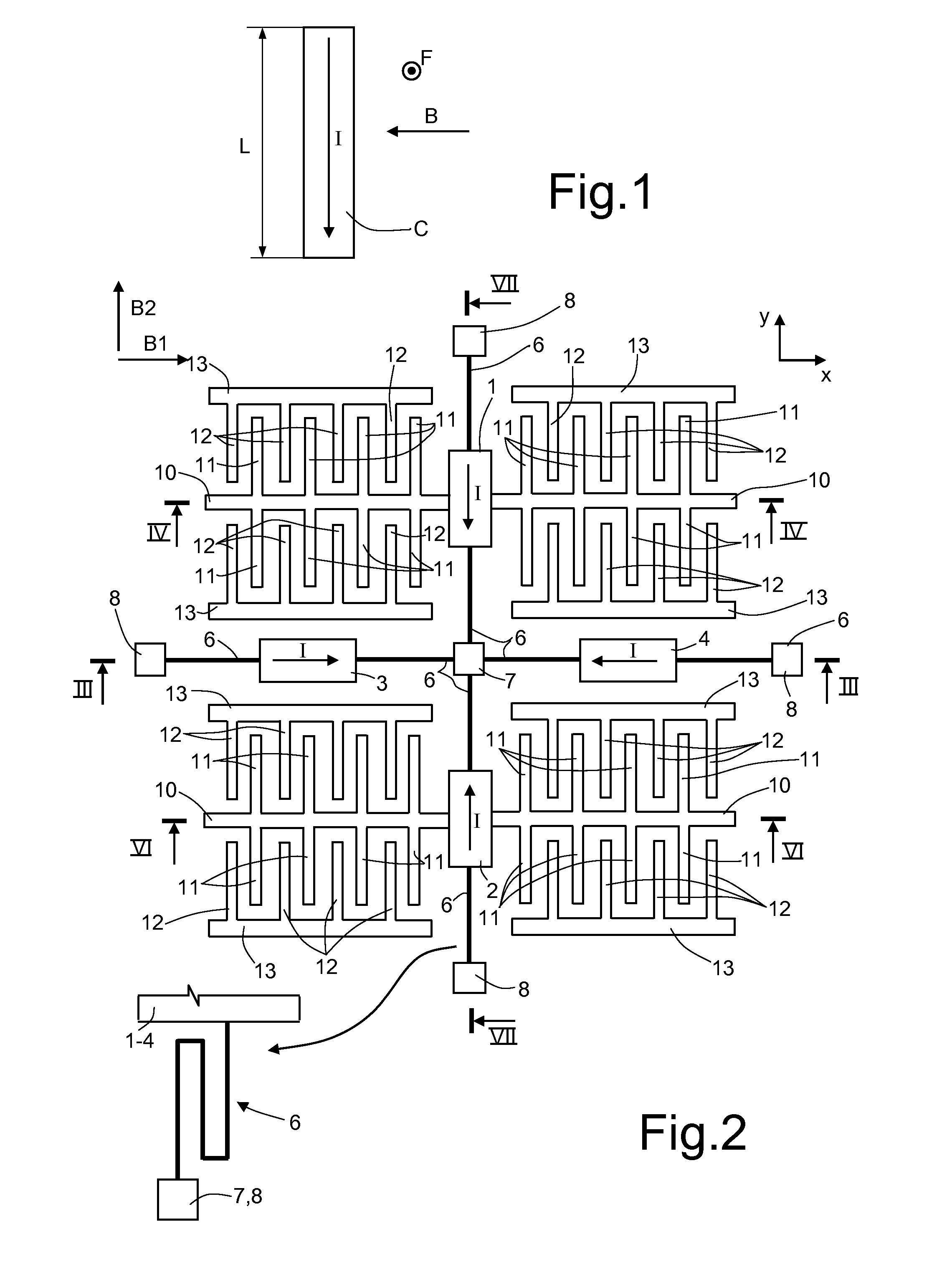
[0030]As is known, the Lorentz force is the force that acts on an electrically charged object that moves in a magnetic field and is always directed perpendicular to the direction of motion. Consequently, since the electric current is constituted by a motion of electrical charges, on the basis of the Lorentz law a conductor C having length L, flowed by a current I and immersed in a magnetic field B (see FIG. 1), is subject to a force F given by:

F=I·L×B

entering the plane of the drawing.

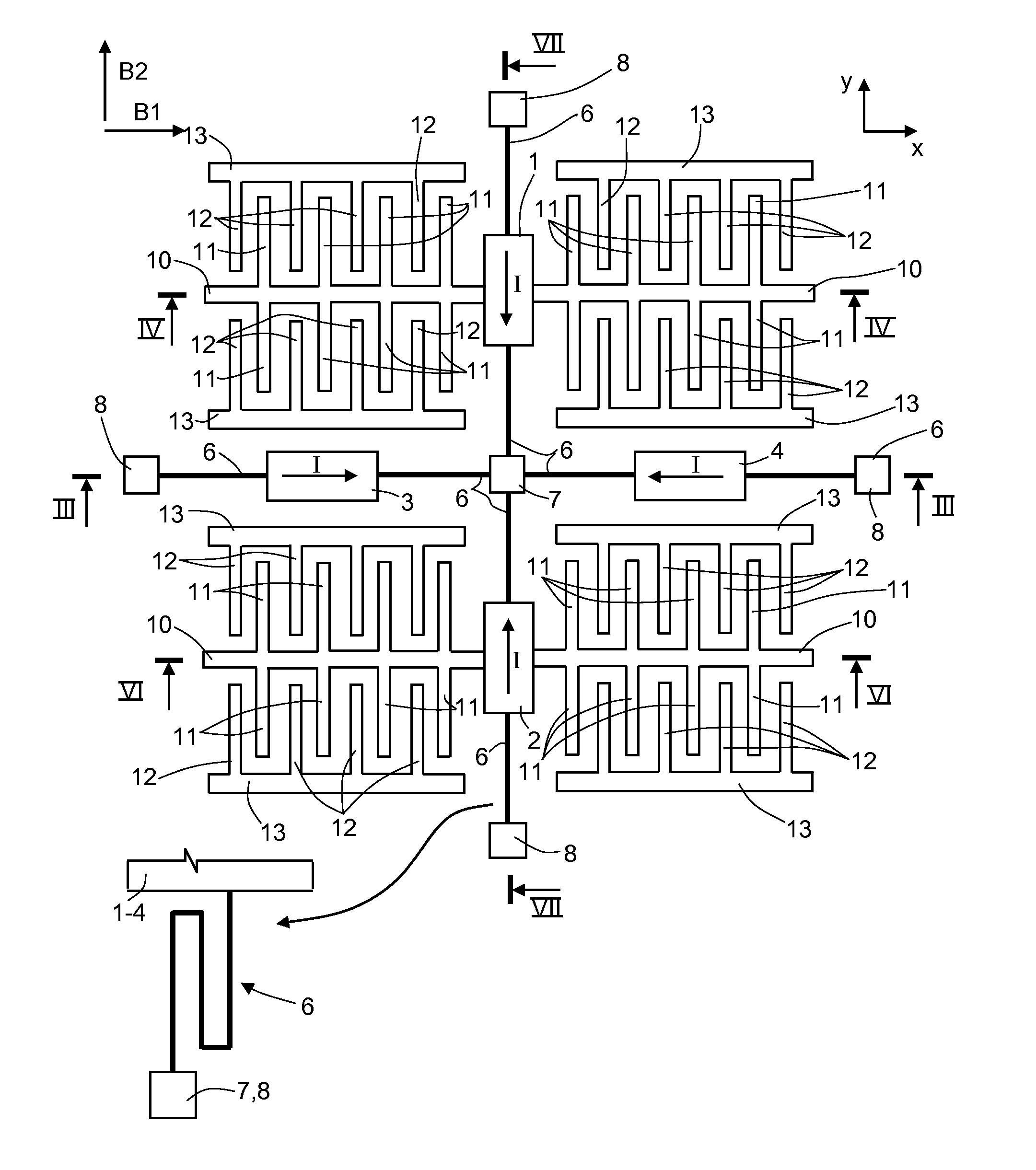
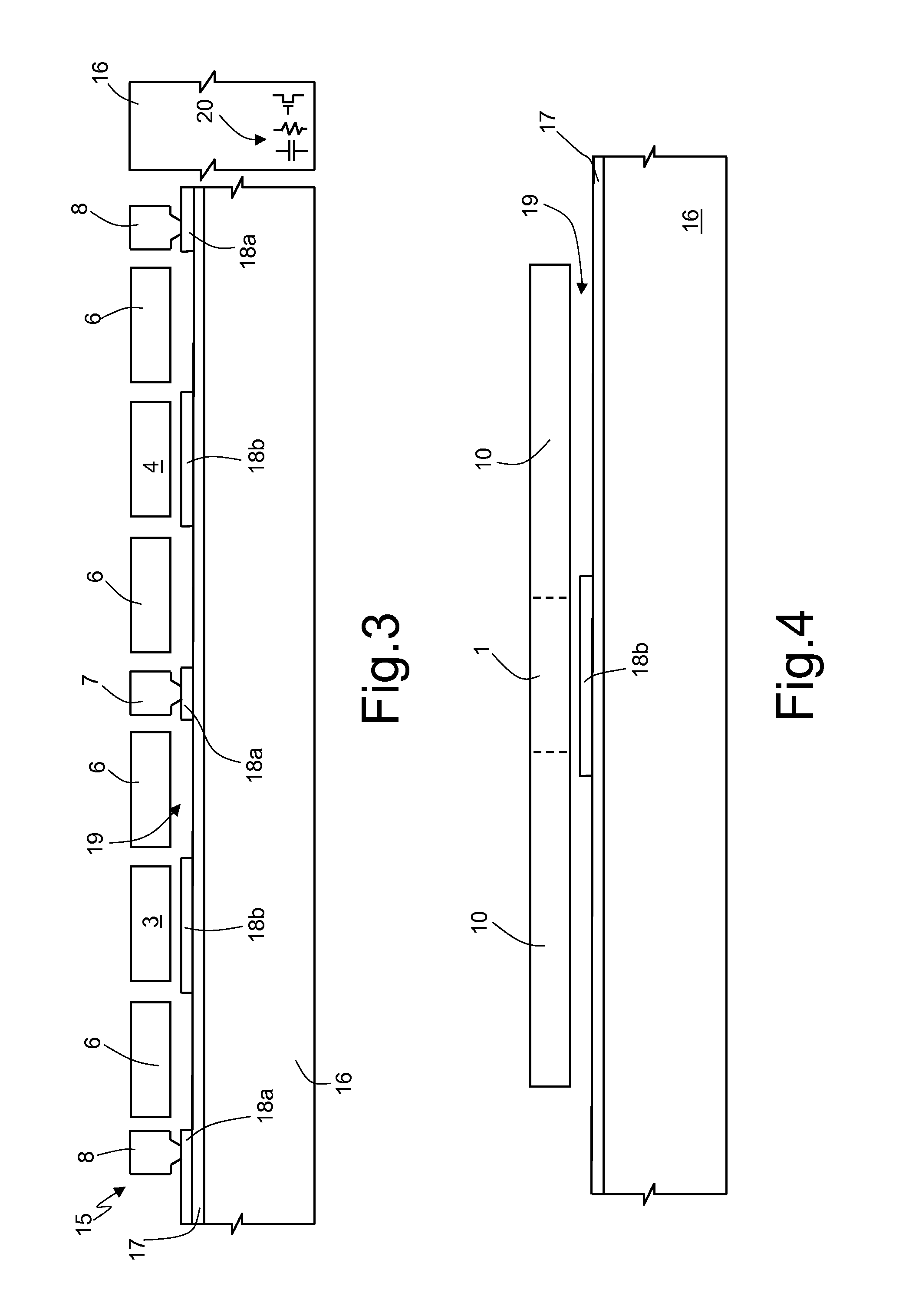
[0031]In the present magnetometer, this force is detected using at least two masses suspended on a substrate (with which they are capacitively coupled) and traversed by respective currents flowing in two mutually perpendicular directions. One of the two masses is connected to mobile electrodes facing respective fixed electrodes. According to the direction ...


PUM


Abstract

Two suspended masses are configured so as to be flowed by respective currents flowing in the magnetometer plane in mutually transversal directions and are capacitively coupled to lower electrodes. Mobile sensing electrodes are carried by the first suspended mass and are capacitively coupled to respective fixed sensing electrodes. The first suspended mass is configured so as to be mobile in a direction transversal to the plane in presence of a magnetic field having a component in a first horizontal direction. The second suspended mass is configured so as to be mobile in a direction transversal to the plane in presence of a magnetic field having a component in a second horizontal direction, and the first suspended mass is configured so as to be mobile in a direction parallel to the plane and transversal to the current flowing in the first suspended mass in presence of a magnetic field having a component in a vertical direction.

Description

BACKGROUND[0001]1. Technical Field[0002]The present disclosure relates to an integrated MEMS magnetometer of semiconductor material formed in MEMS technology.[0003]2. Description of the Related Art[0004]As is known, magnetometers are devices that enable measurement of external magnetic fields, for example the Earth's magnetic field.[0005]Known magnetometers belong to two categories: scalar magnetometers, which are able to measure only the magnitude of the magnetic field; and vector magnetometers, which are able to measure the components of the magnetic field along three axes in space.[0006]Known magnetometers work according to different principles. Older magnetometers are needle compasses, wherein a needle of magnetized material is able to orient itself parallel to the magnetic field. Moreover, known magnetometers are coil magnetometers, which measure the external magnetic field exploiting the electromagnetic induction in a coil; Hall-effect sensors, based upon the measurement of th...

Claims


Application Information

Patent Timeline
Patent Type & Authority Applications(United States)
IPC IPC(8): G01R33/02
CPCG01R33/0005G01R33/038G01R33/0286G01R33/028
Inventor BALDO, LORENZOPROCOPIO, FRANCESCOZERBINI, SARAH
Owner STMICROELECTRONICS SRL
Why Eureka
Try Eureka