Electrochromic Display Device

a display device and electrochromic technology, applied in the field of electrochromic display devices, can solve the problems of display performance degradation, display performance limitation, display time limitation, etc., and achieve the effect of suppressing display performance degradation and superior repetition stability

Inactive Publication Date: 2011-06-16
FUNAI ELECTRIC CO LTD
View PDF3 Cites 11 Cited by
  • Summary
  • Abstract
  • Description
  • Claims
  • Application Information

AI Technical Summary

Benefits of technology

[0018]According to the present invention, there is provided an electrochromic display device including: a first substrate; first electrodes provided on an upper surface of the first substrate; a second substrate provided to be opposed to the first substrate above the first substrate, the second substrate formed of a transparent material; second electrodes provided on an undersurface of the second substrate, at least a part of the second electrodes being formed of a transparent electrode material; and an electrochromic composition layer provided between the first substrate and the second substrate, wherein the electrochromic composition layer contains an electrochromic composition including a supporting electrolyte, a polar solvent, a leuco dye, a hydroquinone derivative an

Problems solved by technology

The displays using these displays have, however, a limitation in places where the displays are read, and the displays are also inferior in their handling in terms of weights, sizes, shapes, and portability, in comparison with the common displays printed on sheets of paper.
Furthermore, because these displays co

Method used


Image

  • Electrochromic Display Device
  • Electrochromic Display Device
  • Electrochromic Display Device

Examples


example 1

Production of Electrochromic Display Device

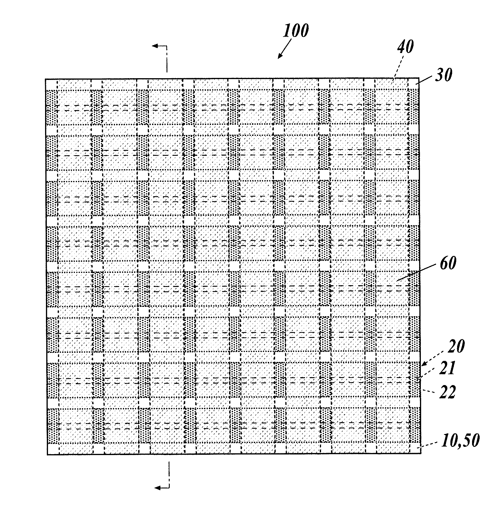
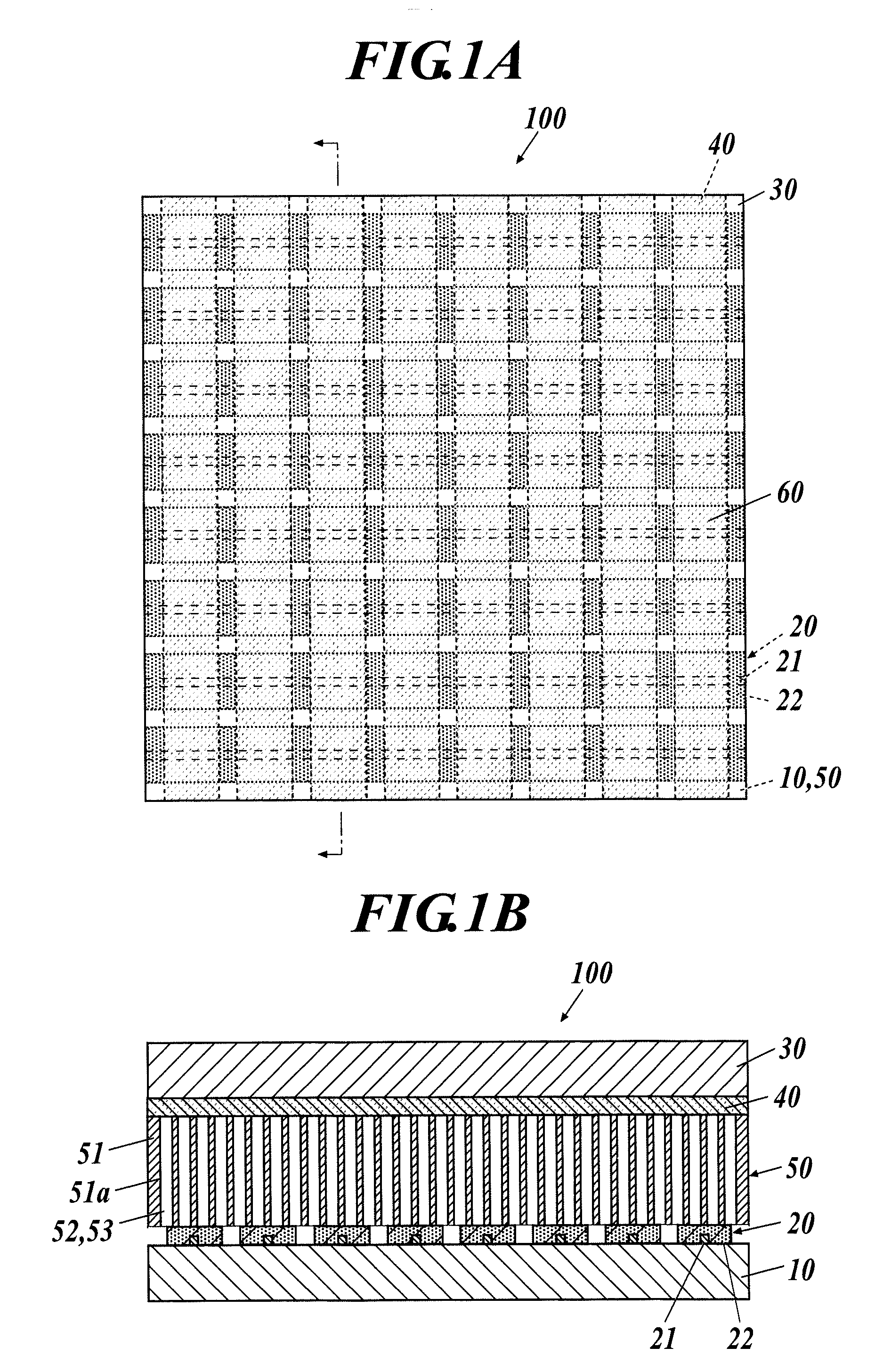
[0159]A rectangular alkali-free glass substrate having a thickness of 0.7 mm was used as the first substrate 10. Chromium was deposited on one surface (upper surface) of the alkali-free glass substrate to be a thickness of 10 nm. Gold was deposited on the chromium to be a thickness of 120 nm. Chromium was deposited on the gold to be a thickness of 10 nm. Thus, a metal film was formed. The metal film formed by the depositions was subjected to patterning by the photolithographic method to be formed in stripes, the width of each of the stripes being 0.025 mm and the pitches 0.45 mm. Thus, the metal electrode portions 21 were formed.

[0160]Next, ITO films were formed by sputtering on the metal electrode portions 21. The ITO films formed by sputtering each had a film thickness of 150 nm. The ITO films formed by sputtering were patterned into stripes, the width of each of the stripes being 0.42 mm and the pitches 0.45 mm, by the photolithographic ...

example 2

Production of Electrochromic Display Device

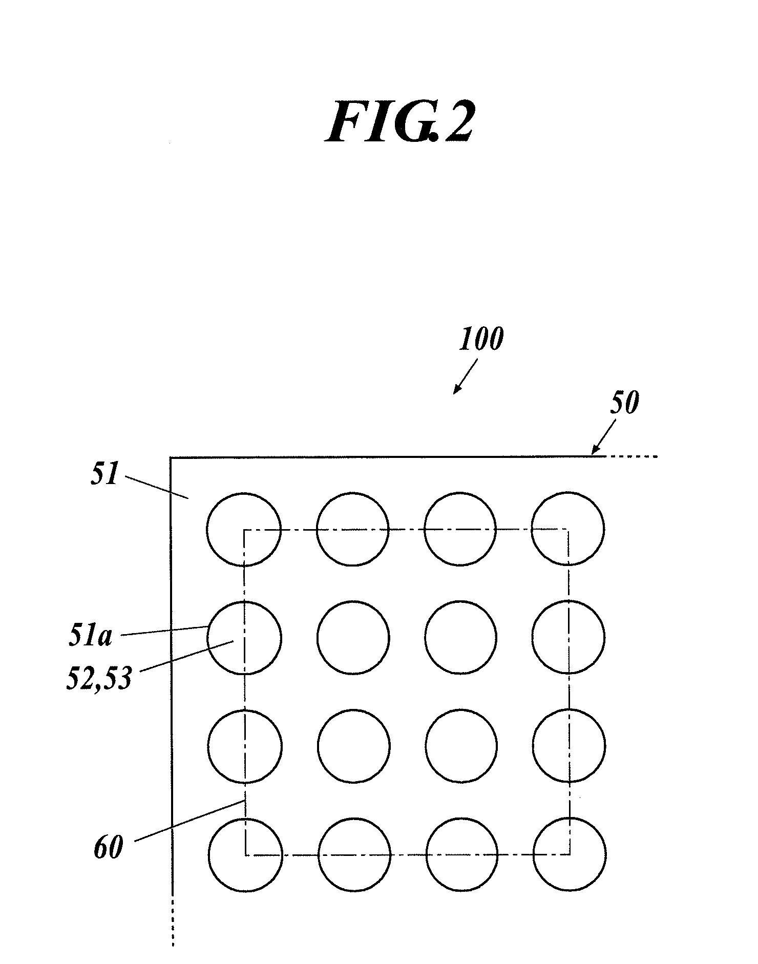
[0231]In order to evaluate the display performances of display devices with a spectrophotometer, in an example 2, an electrochromic display device was produced by using an ITO electrode formed on almost the whole surface of one surface of the first substrate 10 in place of the first electrodes 20 . . . , an ITO electrode formed on almost the whole surface of one surface of the second substrate 30 in place of the second electrodes 40 . . . , and a spacer for holding a certain volume of the electrochromic composition 52 between the first substrate 10 and the second substrate 30 in place of the porous body 51, without adding the absorbent 53 to the electrochromic composition 52.

[0232]To put it concretely, a rectangular alkali-free glass substrate was used as the first substrate 10, and an ITO electrode (hereinafter referred to as a “first ITO electrode”) was formed by forming ITO with sputtering on almost the whole surface of one surface (uppe...


PUM


Abstract

Disclosed is an electrochromic display device, including, a first substrate, first electrodes provided on an upper surface of the first substrate, a second substrate provided to be opposed to the first substrate above the first substrate, the second substrate being formed of a transparent material, second electrodes provided on an undersurface of the second substrate, at least a part of the second electrodes being formed of a transparent electrode material, and an electrochromic composition layer provided between the first substrate and the second substrate. The electrochromic composition layer contains an electrochromic composition including a supporting electrolyte, a polar solvent, a leuco dye, a hydroquinone derivative and/or a catechol derivative, a ferrocene derivative, and a compound having a carbonyl group.

Description

TECHNICAL FIELD[0001]The present invention relates to an electrochromic display device.BACKGROUND ART[0002]Publications in the form of electronic books, i.e. electronic publications, have begun to be actively performed in place of publications produced by conventional printing techniques in association with the spread of electronic information networks. For example, cathode ray tube (CRT) displays and back light type liquid crystal displays are generally used as devices to display electronic information distributed through such networks. The displays using these displays have, however, a limitation in places where the displays are read, and the displays are also inferior in their handling in terms of weights, sizes, shapes, and portability, in comparison with the common displays printed on sheets of paper. Furthermore, because these displays consume large electric power, the displays also have a limitation on their display times in the case where the displays are driven by batteries...

Claims


Application Information

Patent Timeline
IPC IPC(8): G02F1/15
CPCC09K9/02G02F2001/151G02F1/1533C09K2211/187G02F2001/1518
Inventor SUZUKI, MASAOHIGUCHI, TETSUYAWENG, WUFUKUOKA, TOSHIMI
Owner FUNAI ELECTRIC CO LTD
Why Eureka
Try Eureka