
LED bracket weld-free plug-in lamp

a technology of led brackets and plug-in lamps, which is applied in the direction of lighting and heating apparatus, semiconductor devices for light sources, and support devices for lighting and heating, etc. it can solve the problems of shortened service life, premature optical decay of chips, and shorten the service life of chips being heated directly, so as to prevent heat generation, prolong the service life of led chips, and prevent the quality of chips from being undermined

Inactive Publication Date: 2011-06-16
LEE HAN MING
View PDF6 Cites 15 Cited by
  • Summary
  • Abstract
  • Description
  • Claims
  • Application Information

AI Technical Summary

Benefits of technology

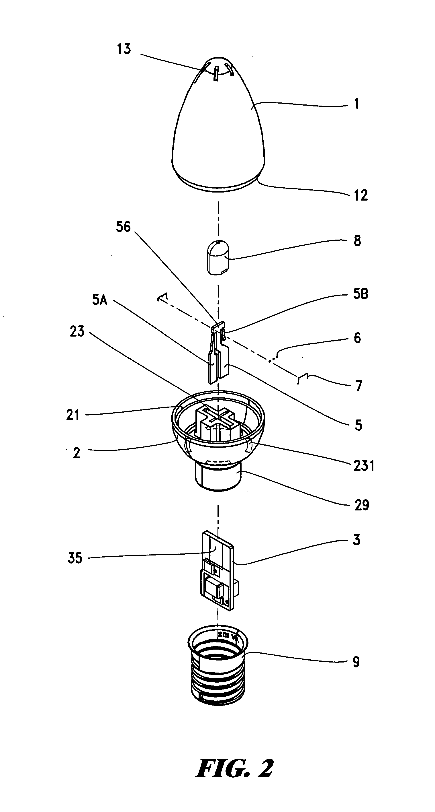
[0002]The primary purpose of the present invention is to provide a LED bracket weld-free plug-in lamp and in particular to one comprising the lamp cover, lamp seat, circuit board, two conducting brackets, chips, conducting wires, transparent adhesive tapes and copper heads to prevent the quality of chips from being undermined due to traditional direct solder fusion and significantly extend the service life of the LED chips.
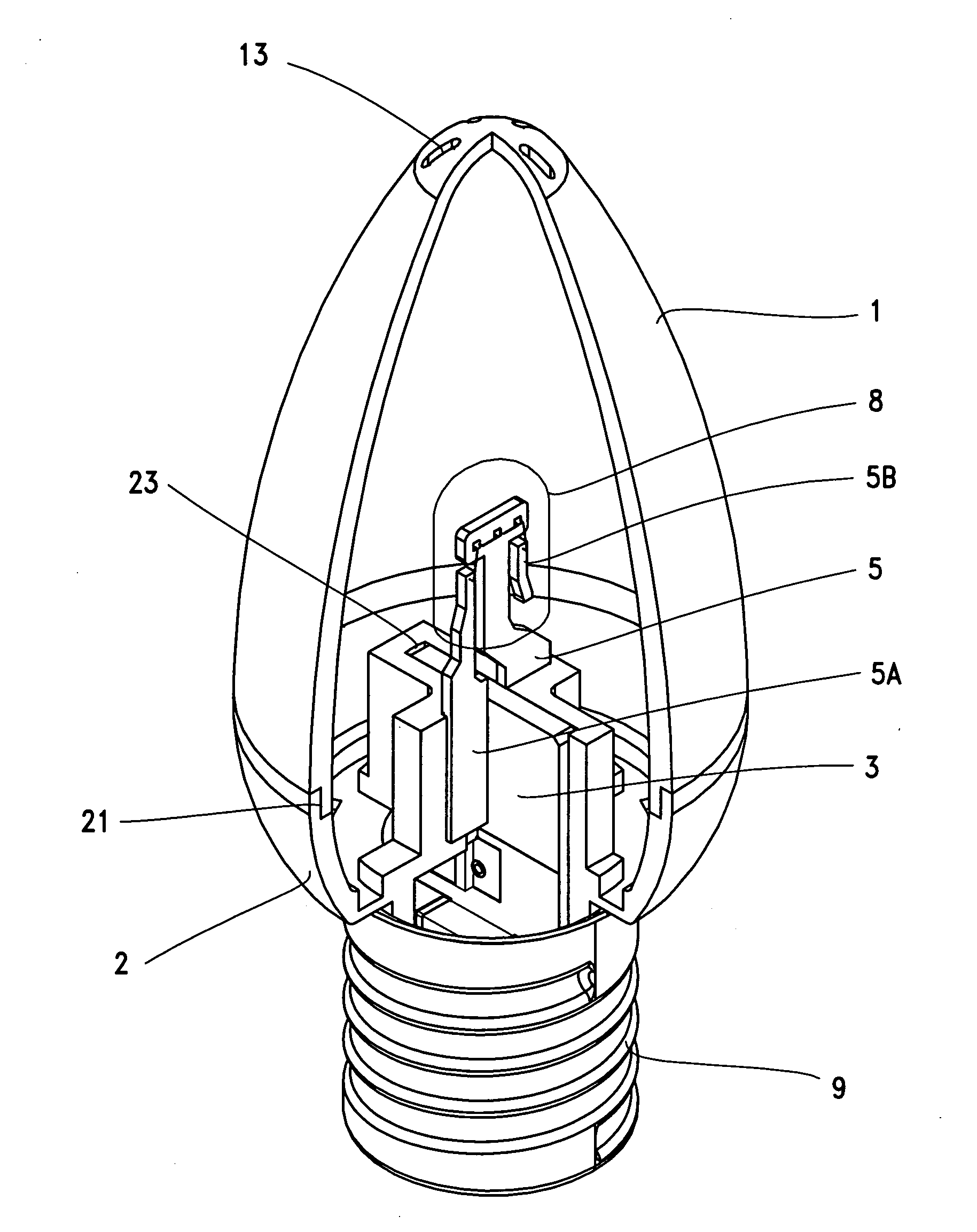
[0003]The secondary purpose of the present invention is to provide a LED bracket weld-free plug-in bracket and in particular to one in which a cross ring groove is provided at the center of the lamp seat so that the circuit board may be embedded and fastened into the groove, and the two conducting brackets are pressed into the fastening device in a crossed manner, and the positive and negative plates on the two sides of the circuit board press tightly into one to stabilize the conducting effect.
[0004]Another purpose of the present invention is to provide a LED bracket weld-free plug-in lamp and in particular to one in which the ring groove is provided for embedding and fastening of the circuit board and two fastening supports in a crossed manner, therefore preventing the heat from traditional direct solder fusion being transferred to the chips and decreasing the efficiency of LED.
[0005]Another purpose of the present invention is to provide a LED bracket weld-free plug-in lamp, wherein the lamp seat and lamp cover are provided with a plurality of radiating holes for convective diffusion of the heat inside the lamp and decreasing the temperature, therefore achieving the industrial application of decreasing the accumulation of heat and reducing the optical decay of the known enclosed structure.

Problems solved by technology

The effect of serious high heat accumulated due to being energized for a long time results in premature optical decay of the chips and shortened service life.
In particular, the welded circuit board of the chip cup bracket needs to be fully fused with solder at high temperature so that the bracket and circuit board are welded firmly together; during the process of fusing with solder at high temperatures, the heat is transferred along the bracket to the chips above the bracket within a very short period of time, therefore significantly shortening the service life of the chips being heated directly.

Method used


Image

  • LED bracket weld-free plug-in lamp
  • LED bracket weld-free plug-in lamp
  • LED bracket weld-free plug-in lamp

Examples


Embodiment Construction

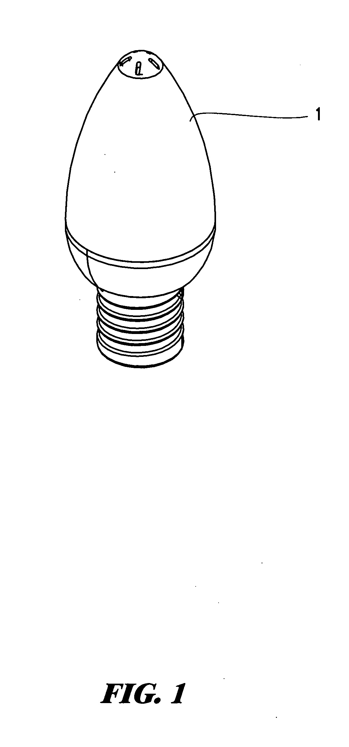
[0017]Please refer to FIGS. 1 through FIGS. 6. The present invention relates to a LED bracket weld-free plug-in lamp, comprising the lamp cover 1, lamp seat 2, circuit board 3, two conducting brackets 5 and 5A, chip 6, conducting wire 7, transparent adhesive tap 8 and copper head 9; the lamp cover 1 is an open thin cover made of light-transmitting material, the opening is provided with lower ring diameter or thread 12, and its sealing is provided with equally spaced radiating holes 13; the lamp seat 2 is a lamp seat made of light-transmitting material in relative to the opening of the lamp cover 1, the opening of the lamp seat is provided with expanded ring diameter or thread 21 for embedding or screwing into place of the lower ring diameter or thread 12 of the lamp cover, the center of the lamp is provided with cross ring groove 23, the outer ring of the cross ring groove is provided with a plurality of radiating holes 231 at the lamp seat, and a snap ring 29 projects downward from...


PUM


Abstract

The present invention relates to a LED bracket weld-free plug-in lamp, comprising the lamp cover, lamp seat, circuit board, two conducting brackets, chips, conducting wires, transparent adhesive tapes and copper heads, wherein a cross ring groove is provided at the center of the lamp seat for embedding and fastening of the circuit board so that the two conducting brackets are pressed in and inserted and the positive and negative plates on the two sides of the circuit board press tightly into one to stabilize the conducting effect, prevent the quality of chips from being undermined due to traditional direct solder fusion and significantly extend the service life of the LED chips.

Description

BACKGROUND OF THE INVENTION[0001]In recent years, the power-saving LED lamps have replaced the traditional tungsten filament bulbs and been widely used in a wide variety of electronic products. The lighting principle is that chips are built inside the chip cup above the bracket and a circuit board is welded below the bracket to input power and generate the trigger light source. The effect of serious high heat accumulated due to being energized for a long time results in premature optical decay of the chips and shortened service life. In particular, the welded circuit board of the chip cup bracket needs to be fully fused with solder at high temperature so that the bracket and circuit board are welded firmly together; during the process of fusing with solder at high temperatures, the heat is transferred along the bracket to the chips above the bracket within a very short period of time, therefore significantly shortening the service life of the chips being heated directly.SUMMARY OF T...

Claims


Application Information

Patent Timeline
IPC IPC(8): F21V21/00
CPCF21Y2101/02F21K9/135F21V23/005F21V19/0025F21K9/232F21Y2115/10F21K9/238
Inventor LEE, HAN-MING
Owner LEE HAN MING
Learn More