Source sound separator with spectrum analysis through linear combination and method therefor

a source sound and linear combination technology, applied in the field of source sound separator and a method therefor, can solve the problems of insufficient control of directivity characteristics, voice captured by a microphone may severely be deteriorated in voice recognition precision, and achieve the effect of optimum sound quality and easy separation

Active Publication Date: 2011-06-16
OKI ELECTRIC IND CO LTD +1
View PDF1 Cites 15 Cited by
  • Summary
  • Abstract
  • Description
  • Claims
  • Application Information

AI Technical Summary

Benefits of technology

[0012]In accordance with the present invention, a computer program is provided which controls a computer, when installed in and executed on the computer, to separate a target sound and an interfering sound from each other by causing the computer to operate as the source sound separator stated above.
[0013]According to the present invention, a source sound may thus readily be separated even when there are plural interfering sounds. In addition, the target sound as separated may be of optimum sound quality.

Problems solved by technology

In exploiting voice recognition or telephone message recording, there may be raised such a problem that the voice captured by a microphone may severely be deteriorated in precision of voice recognition by ambient noise, or that the recorded voice may become hardly perceptible due to such noise.
However, simply controlling the directivity characteristics is not sufficient if it is intended to take out the voice of interest in a state separated from the background noise.
If there are three or more sound sources, these signals could theoretically be separated one from another whereas the performance of separation would severely be deteriorated.
Thus, if there are plural noise sources, it becomes extremely difficult to separate the target sound to high precision from the received sound signal corrupted with multiple noise signals.
However, the signal captured by a microphone may contain an interfering sound in addition to a target sound.
Hence, it cannot but be said that those solutions are improper to use in the vicinity of the last stage of elimination of the interfering sound.
Under such a situation, the sound quality is deteriorated after ultimate source sound separation.

Method used


Image

  • Source sound separator with spectrum analysis through linear combination and method therefor
  • Source sound separator with spectrum analysis through linear combination and method therefor
  • Source sound separator with spectrum analysis through linear combination and method therefor

Examples


Embodiment Construction

[0019]For better understanding the present invention, the method of source sound separation, disclosed in Kobayashi et al, will now be described in detail with reference to FIG. 3, prior to describing preferred embodiments of the present invention.

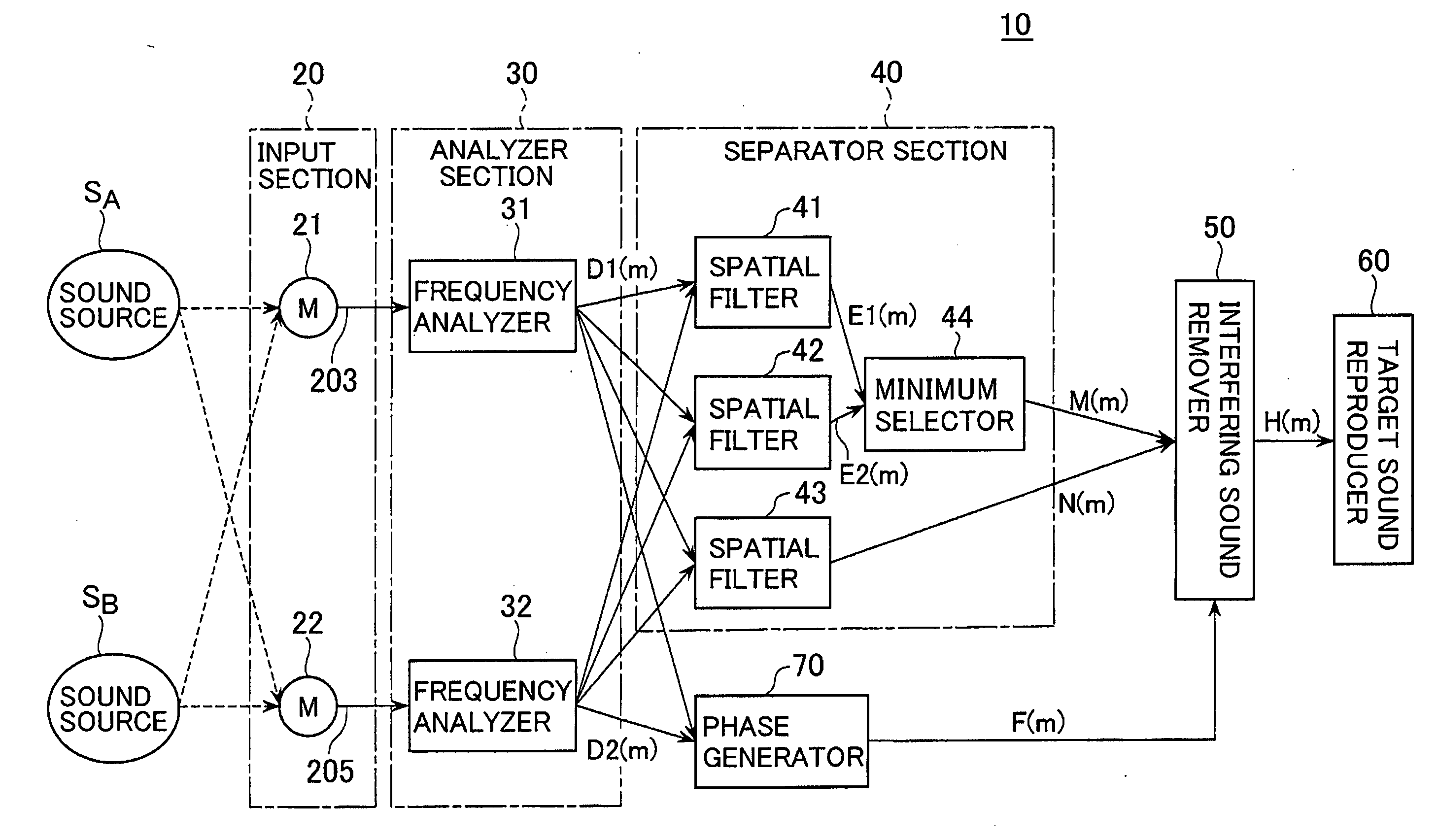
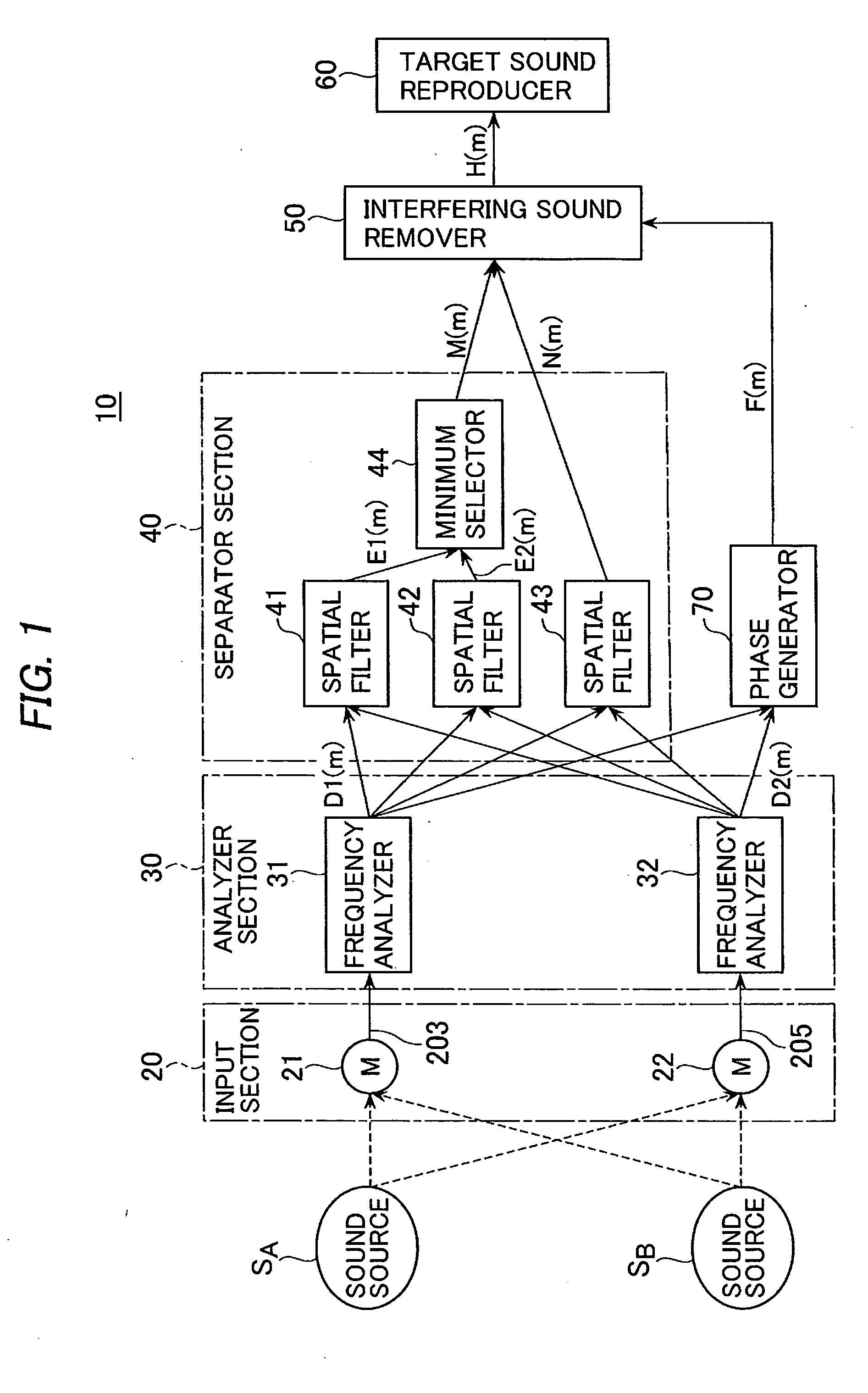
[0020]In the method of Kobayashi et al., two microphones 21 and 22 are arrayed side-by-side for extending in a direction substantially perpendicular to the direction of an incoming target sound.

[0021]In a target sound superior signal generator 330, a first target sound superior signal generator 331 takes a difference between a received sound signal X1(t) of the microphone 21 and a signal D(X2(t)) in the time or frequency domain, the latter signal D(X2(t)) being obtained by delaying the received sound signal of the microphone 22. This difference taken yields a first target sound superior signal X1(t)-D(X2(t)). A second target sound superior signal generator 332 takes a difference between a received sound signal X2(t) of the microphone 22 an...


PUM


Abstract

In a source sound separator, first and second target sound predominant spectra are generated respectively by first and second processing operations for linear combination for emphasizing the target sound, using received sound signals of two microphones arrayed at a distance from each other. A target sound suppressed spectrum is generated by processing for linear combination for suppression of the target sound, using the two received sound signals. Further, a phase signal containing a larger amount of signal components of the target sound and exhibiting directivity in the direction of the target sound is generated by processing of linear combination, using the two received sound signals. The target sound and the interfering sound are separated from each other using the first and second target sound predominant spectra, the target sound suppressed spectrum, and the phase signal.

Description

BACKGROUND OF THE INVENTION[0001]1. Field of the Invention[0002]The present invention relates to a source sound separator and a method therefor, and more particularly to a source sound separator and a method for separating a target voice with an interfering sound isolated which comes from a direction other than the direction of the target voice.[0003]2. Description of the Background Art[0004]Such a source sound separator is applicable to, e.g. a mobile device, such as a mobile phone, or a vehicle-laden device, such as a car navigation system. In exploiting voice recognition or telephone message recording, there may be raised such a problem that the voice captured by a microphone may severely be deteriorated in precision of voice recognition by ambient noise, or that the recorded voice may become hardly perceptible due to such noise. Under such circumstances, attempts have been made to use a microphone array to control the directivity characteristics to thereby selectively get just t...

Claims


Application Information

Patent Timeline
Patent Type & Authority Applications(United States)
IPC IPC(8): H04R3/00G10L21/0272G10L21/028G10L21/0308
CPCG10L2021/02166G10L21/0272
Inventor MORITO, MAKOTOYAZU, TAKASHIYAMADA, KEIKOBAYASHI, TETSUNORIAKAGIRI, KENZOOGAWA, TETSUJI
Owner OKI ELECTRIC IND CO LTD
Why Eureka
Try Eureka