

Battery case
a battery case and battery technology, applied in the field of battery cases, can solve the problems of occupying a large loading space and a large weight of the battery in the vehicle, and achieve the effects of excellent effect, high sealability, and strong rigidity of the battery cas
- Summary
- Abstract
- Description
- Claims
- Application Information
AI Technical Summary
Benefits of technology
Problems solved by technology
Method used
Image

Examples
embodiment 1
[0022]Embodiment 1 of the present invention will now be described.
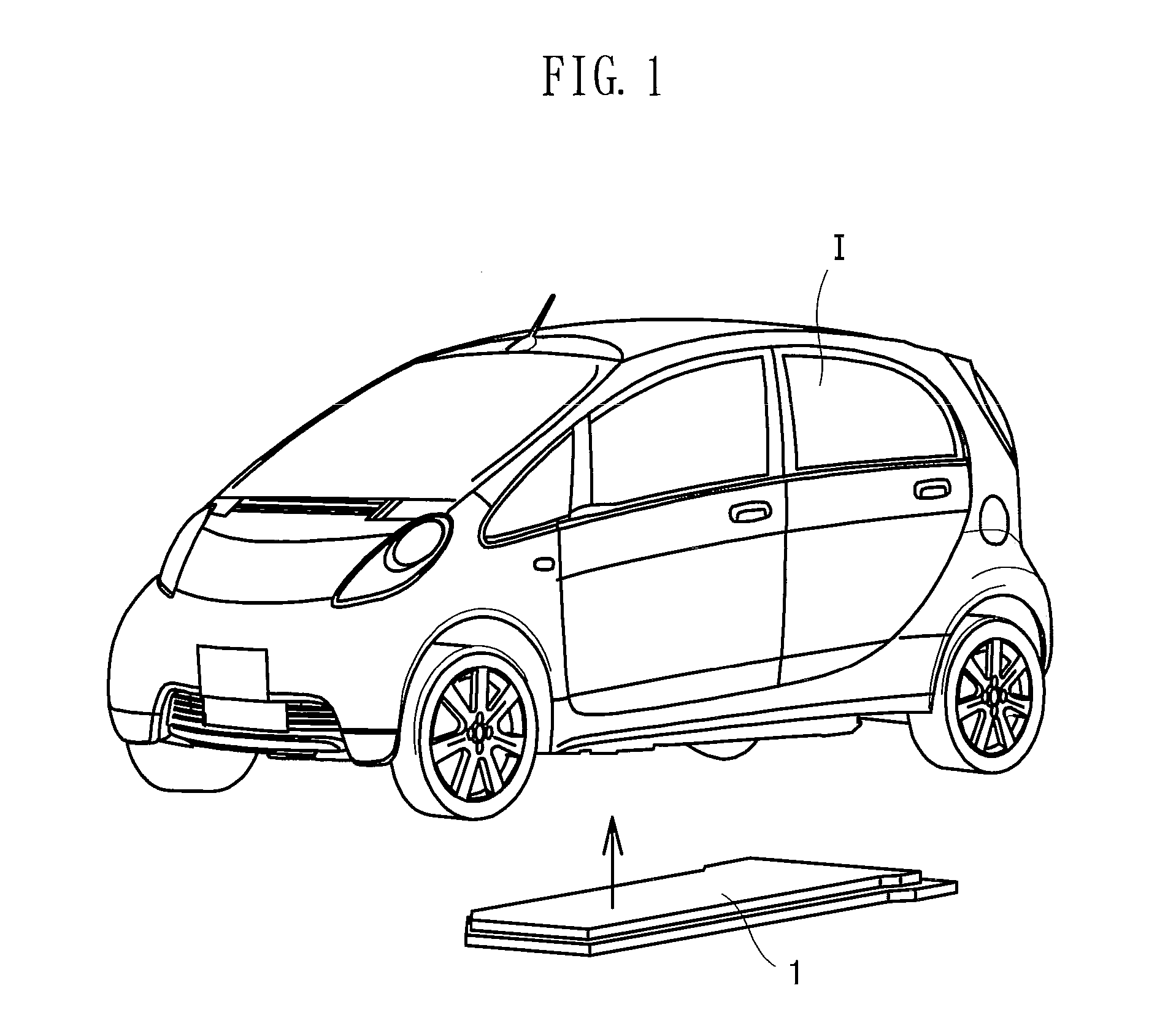
[0023]A battery case is intended to accommodate batteries within an accommodation space formed inside. As shown in FIG. 1, for example, a battery case 1 is installed in a lower part of the vehicle body of an electric vehicle I by a member for battery installation (not shown) to supply electricity to a motor or the like of the electric vehicle I. The configuration of the battery case 1 will be described in detail below using FIGS. 2 to 4.
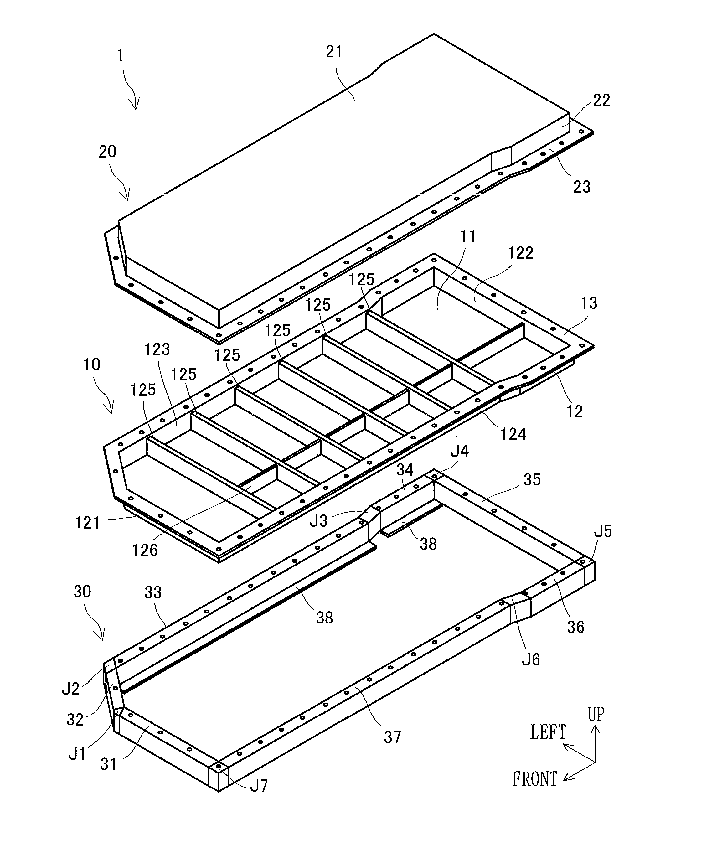
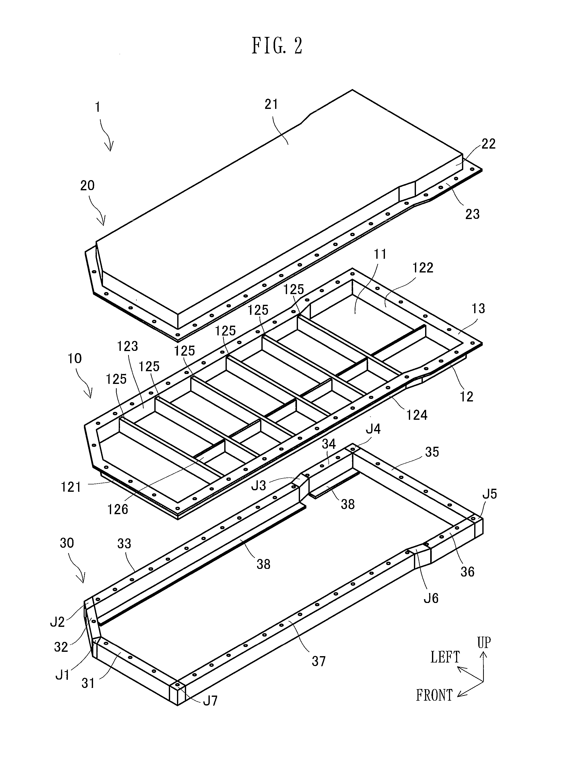
[0024]Concretely, the battery case 1 has a battery tray 10 loaded with a plurality of batteries V (see FIG. 3B, a battery cover 20 provided on the upper surface side of the battery tray 10 for sealing the battery tray 10, and a housing-shaped frame 30 for covering the outer periphery of the battery tray 10 and reinforcing the battery tray 10.
[0025]The battery tray 10 constitutes a lower part of the battery case 1, and is composed of a thin-walled (thickness 3 to 5 mm) resin. The batter...
embodiment 2
[0045]Embodiment 2 of the present invention will be described by reference to FIG. 5. In FIG. 5, the same members as those in FIGS. 1 to 4 are assigned the same numerals as in FIGS. 1 to 4.
[0046]In Embodiment 1, each metal frame constituting the housing-shaped frame is provided with the beam portions 39 (see FIG. 4) throughout its lateral dimension in the vicinity of its middle. In the present embodiment, by contrast, each metal frame constituting a housing-shaped frame 30A is not provided with the beam portions. In this case, the battery case 1 can be rendered more lightweight than that in Embodiment 1. The housing-shaped frame 30A in the present embodiment can be constructed of a square steel pipe, for example. In Embodiment, moreover, the frame-side flange portions are integrated with the housing-shaped frame. In the present embodiment, however, frame-side flange portions 38A may be separate from the housing-shaped frame 30A. In this case, the housing-shaped frame 30A and the fra...
embodiment 3
[0048]Embodiment 3 of the present invention will be described by reference to FIG. 6. In FIG. 6, the same members as those in FIGS. 1 to 5 are assigned the same numerals as in FIGS. 1 to 5.
[0049]In Embodiment 1, the hollow metal frames are joined to constitute the housing-shaped frame 30. In the present embodiment, a housing-shaped frame 30C is constituted by roll-formed sheet metals. That is, sheet metals are roll-formed such that two rectangular portions 30D of a nearly rectangular shape, as viewed in cross section, are formed. Then, near the middle part between the two rectangular portions 30D, the widthwise central part and the end part of the sheet metals are joined together by spot welding. That is, the housing-shaped frame 30C is formed in such a state that two frames are joined together in the vertical direction. By adopting such a form, the housing-shaped frame 30C can retain strength and rigidity, and can be produced relatively easily and simply.
[0050]In this case as well,...
PUM
| Property | Measurement | Unit |
|---|---|---|
| thickness | aaaaa | aaaaa |
| thickness | aaaaa | aaaaa |
| weight | aaaaa | aaaaa |
Abstract
Description
Claims
Application Information