Fuel cell system

a fuel cell and system technology, applied in the field of fuel cell systems, can solve the problems of inability to achieve desired maintenance performance, heat and fluid diffusion in the low temperature section, etc., and achieve the effects of reducing heat diffusion, ensuring stability, and ensuring maintenan

Active Publication Date: 2011-06-16
HONDA MOTOR CO LTD
View PDF10 Cites 8 Cited by
  • Summary
  • Abstract
  • Description
  • Claims
  • Application Information

AI Technical Summary

Benefits of technology

[0011]The present invention has been made to solve the problem of this type, and an object of the present invention is to provide a fuel cell system in which respective devices are disposed depending on the operating temperature range and the function in order to minimize diffusion of heat and fluid and prevent, as much as possible, heat influence on the devices that are used at relatively low temperature, and which is capable of being placed along the wall suitably, being stably disposed, and ensuring ease of maintenance.

Problems solved by technology

Therefore, in particular, in the case where a high temperature fuel cell (such as a solid oxide fuel cell or a molten carbonate fuel cell) or a medium temperature fuel cell (such as a phosphoric acid fuel cell and a hydrogen membrane fuel cell) is used, the low temperature section which should be maintained at low temperature tends to be affected by diffusion of heat and fluid.
Further, the desired maintenance performance cannot be achieved.

Method used


Image

  • Fuel cell system
  • Fuel cell system
  • Fuel cell system

Examples


first embodiment

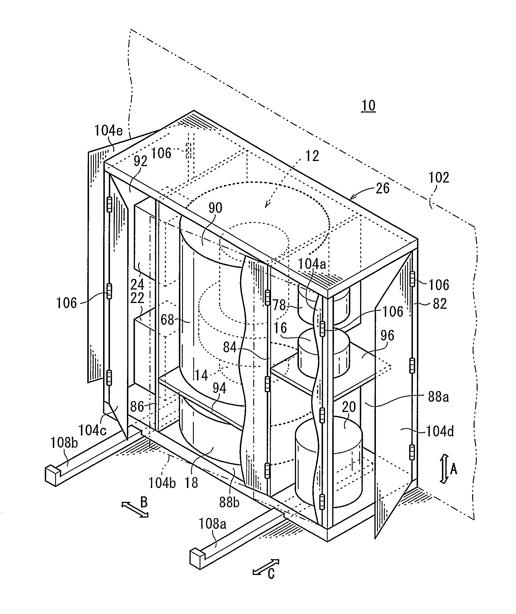
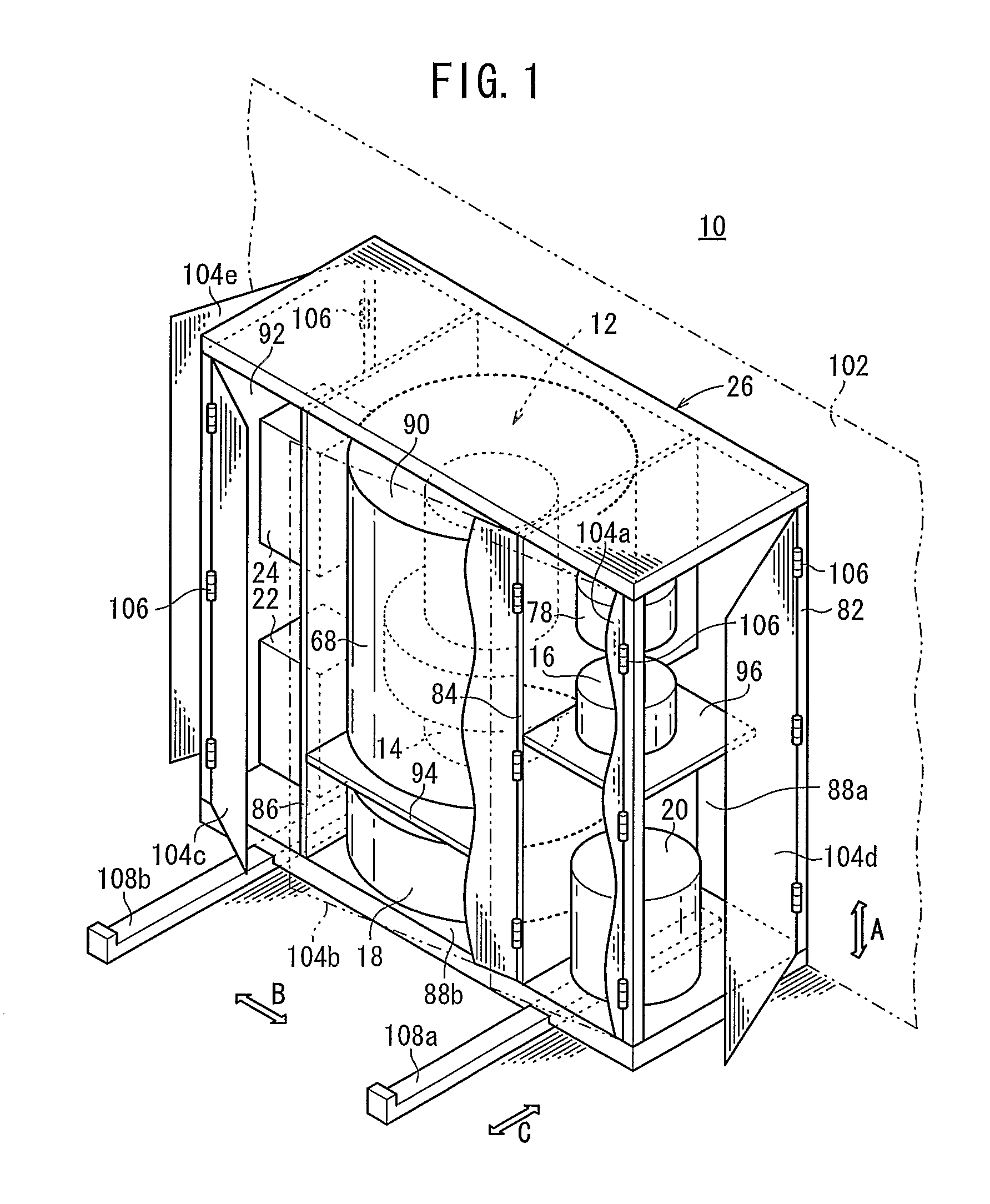
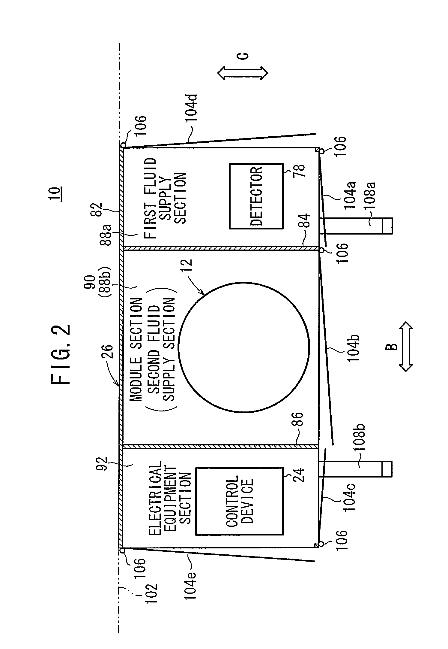
[0047]A fuel cell system 10 according to the present invention is used in various applications, including stationary and mobile applications. For example, the fuel cell system 10 is mounted on a vehicle. As shown in FIGS. 1 to 4, the fuel cell system 10 includes a fuel cell module 12 for generating electrical energy in power generation by electrochemical reactions of a fuel gas (hydrogen gas) and an oxygen-containing gas (air), a combustor 14 for raising the temperature of the fuel cell module 12, a fuel gas supply apparatus (including a fuel gas pump) 16 for supplying the fuel gas to the fuel cell module 12, an oxygen-containing gas supply apparatus (including an air pump) 18 for supplying an oxygen-containing gas to the fuel cell module 12, a water supply apparatus (including a water pump) 20 for supplying water to the fuel cell module 12, a power converter 22 for converting the direct current electrical energy generated in the fuel cell module 12 to electrical energy according to...

second embodiment

[0094]The fuel cell system 120 includes a casing 122 having a plurality of wheels 124 at the bottom of the casing 122. Therefore, in the second embodiment, the casing 122 is movable in various directions arbitrarily and easily by the wheels 124. Thus, the first fluid supply section 88a, the second fluid supply section 88b, the module section 90, and the electrical equipment section 92 can be positioned easily at a position where operation by the operator can be performed smoothly, so that the operator can perform various operations easily.

[0095]In the second embodiment, although only the wheels 124 are provided, both of the wheels 124 and the slide rails 108a, 108b may be used in combination.

third embodiment

[0096]FIG. 8 is a perspective view schematically showing a fuel cell system 130 according to a FIG. 9 is a plan view showing an operating state of the fuel cell system 130.

[0097]The fuel cell system 130 includes a casing 132 having a first case unit 132a, a second case unit 132b, and a third case unit 132c separately. The first fluid supply section 88a is formed in the first case unit 132a, the module section 90 and the second fluid supply section 88b are formed in the second case unit 132b, and the electrical equipment section 92 is formed in the third case unit 132c.

[0098]The first case unit 132a is movable back and forth in the direction indicated by the arrow C along a slide rail 134a. The second case unit 132b is movable back and forth in the direction indicated by the arrow C along a slide rail 134b. The third case unit 132c is movable back and forth in the direction indicated by the arrow C along a slide rail 134c. The first case unit 132a, the second case unit 132b, and th...


PUM

PropertyMeasurementUnit
operating temperatureaaaaaaaaaa
temperatureaaaaaaaaaa
electrical energyaaaaaaaaaa

Abstract

A casing of a fuel cell system is divided into a first fluid supply section, a second fluid supply section, a module section, and an electrical equipment section. A water supply apparatus, a fuel gas supply apparatus, and a detector are provided in the first fluid supply section. An oxygen-containing gas supply apparatus is provided in the second fluid supply section. A fuel cell module and a combustor are provided in the module section. A power converter and a control device are provided in the electrical equipment section. The module section is interposed between the first fluid supply section and the electrical equipment section. The second fluid supply section is disposed on the lower surface of the module section.

Description

TECHNICAL FIELD [0001]The present invention relates to a fuel cell system including a fuel cell module, a combustor, a fuel gas supply apparatus, an oxygen-containing gas supply apparatus, a water supply apparatus, a power converter, a control device, and a casing containing the fuel cell module, the combustor, the fuel gas supply apparatus, the oxygen-containing gas supply apparatus, the water supply apparatus, the power converter, and the control device.BACKGROUND ART [0002]Typically, a solid oxide fuel cell (SOFC) employs a solid electrolyte of ion-conductive solid oxide such as stabilized zirconia. The electrolyte is interposed between an anode and a cathode to form an electrolyte electrode assembly (MEA). The electrolyte electrode assembly is interposed between separators (bipolar plates). In use, normally, predetermined numbers of the electrolyte electrode assemblies and the separators are stacked together to form a fuel cell stack.[0003]As the fuel gas supplied to the fuel ce...

Claims


Application Information

Patent Timeline
Patent Type & Authority Applications(United States)
IPC IPC(8): H01M8/06H01M8/04
CPCH01M8/0606H01M8/2465H01M8/2475Y02E60/525H01M2250/10Y02E60/50Y02B90/14H01M2008/1293Y02B90/10
Inventor OGAWA, TETSUYAFUJISAWA, KIMIKO
Owner HONDA MOTOR CO LTD
Why Eureka
Try Eureka