Fixing device and image forming apparatus using the same

a technology of fixing device and image forming apparatus, which is applied in the direction of electrographic process apparatus, instruments, optics, etc., can solve the problems of wasting energy consumed by other than image forming operations, and achieve the effects of efficient conversion of input power into heat energy, efficient conductance of heat from the heating member, and increased heating valu

Active Publication Date: 2012-05-17
SHARP KK
View PDF14 Cites 1 Cited by
  • Summary
  • Abstract
  • Description
  • Claims
  • Application Information

AI Technical Summary

Benefits of technology

[0033]According to the second aspect of the present invention, it is possible to cover the fixing roller by taking up the minimum cross section so as to achieve the maximum use of heat from the backside of the heating member.
[0034]According to the third aspect of the present invention, for example, since a main heat generator and sub heat generators having different heating values are arranged in the curved plate-shaped heat generator with respect to the circumferential direction of the fixing roller, it is possible to efficiently convert input power into heat energy.
[0035]According to the fourth aspect of the present invention, by increasing the heating value at the area where the fixing belt and the fixing member come into hermetic contact with each other, it is possible to efficiently conduct heat from the heating member to the fixing belt.
[0036]According to the fifth aspect of the present invention, it is possible to inhibit radiation of heat from the surface of the fixing belt.
[0037]According to the sixth aspect of the present invention, the surface of the fixing belt is covered by taking up the minimum cross section, so that is possible to minimize diffusion of heat from the fixing belt.
[0038]According to the seventh aspect of the present invention, it is possible to alleviate loss of heat energy in the fixing device, hence provide an image forming apparatus that can shorten its warm-up time and is excellent in energy saving performance.

Problems solved by technology

However, since the fixing and pressing rollers of the conventional paired roller type remain at room temperature when the image forming apparatus is turned on at the time of the first activation in the morning, the surface temperature of the rollers needs to be raised to a predetermined temperature after power activation, which requires warm-up time.
In this way, the conventional configurations have the problem that waste energy is consumed by other than an image forming operation.

Method used


Image

  • Fixing device and image forming apparatus using the same
  • Fixing device and image forming apparatus using the same
  • Fixing device and image forming apparatus using the same

Examples


example 1

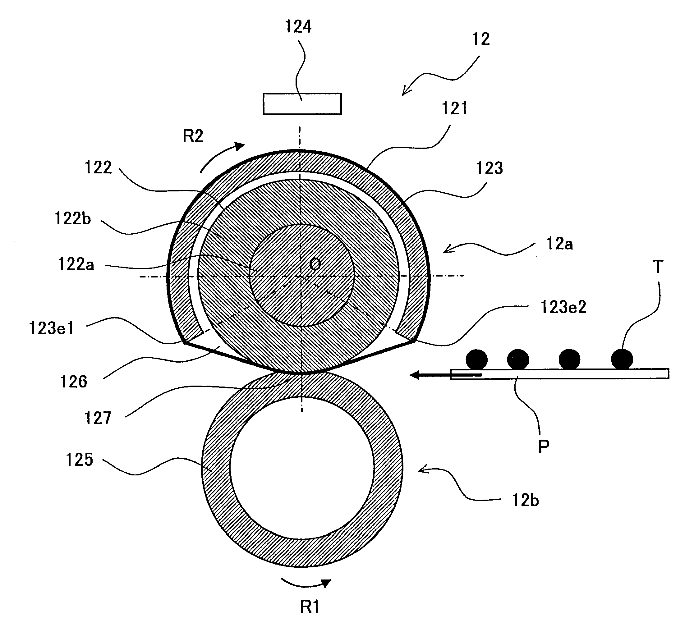
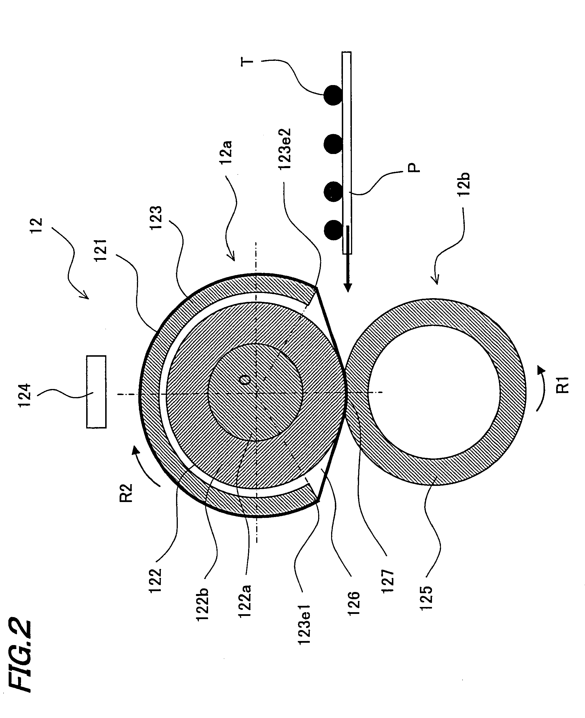
[0119]Next, an example of fixing unit 12 of the present embodiment will be described with reference to the drawings.

[0120]FIG. 3 is an illustrative view showing a configuration of example 1 of a fixing part that constitutes the fixing unit of the present embodiment. FIG. 4A is an illustrative view showing a layered structure of a heating member of the fixing part that constitutes the fixing unit of the present embodiment. FIG. 4B is an illustrative plan view showing a pattern of the heating member.

[0121]A fixing unit 120 of example 1 has the same overall configuration as that of fixing unit 12 of the embodiment. In the description of fixing unit 120, the same components as those of the fixing unit of the embodiment are allotted with the same reference numerals without description.

[0122]In fixing unit 120 of example 1, a belt-like member, having a diameter of 36 mm, and formed of a base of polyimide of 50 μm thick, an elastic layer of silicone rubber of 150 μm thick and a separation ...

example 2

[0142]Next, another configuration of a fixing unit 12 of the present embodiment will be described taking an example 2 with reference to the drawings.

[0143]FIG. 5 is an illustrative view showing a configuration of example 2 of a fixing part that constitutes the fixing unit of the present embodiment. FIG. 6 is an illustrative plan view showing a pattern of a heating member of the fixing part.

[0144]A fixing unit 220 of example 2 has the same configuration as that of the fixing unit of example 1 except for the structure of heating member 223. So, in the description of fixing unit 220, the same components as those of the fixing unit of example 1 are allotted with the same reference numerals without description.

[0145]Fixing unit 220 of example 2 is adapted so that distribution of heat generation from a heating member 223 (heater: curved plate-shaped heat generator) is made uneven with respect to the circumferential direction of fixing roller 122, as shown in FIG. 5. Specifically, heating ...

example 3

[0156]Next, another configuration of a fixing unit 12 of the present embodiment will be described taking an example 3 with reference to the drawings.

[0157]FIG. 7 is an illustrative view showing a configuration of example 3 of a fixing part that constitutes the fixing unit of the present embodiment.

[0158]A fixing unit 320 of example 3 has the same configuration as that of the fixing unit of example 1 except for the configuration of an insulating member 330. So, in the description of fixing unit 320, the same components as those of the fixing unit of example 1 are allotted with the same reference numerals without description.

[0159]In fixing unit 320 of example 3, insulating member 330 that covers the outer peripheral side of heating member 123 via fixing belt 121 is arranged close to the outer peripheral side of fixing belt 121 in a range where fixing belt 121 comes into contact with heating member 123, as shown in FIG. 7.

[0160]Insulating member 330 has a circular arc cross-section cu...


PUM


Abstract

An image forming apparatus includes photoreceptor drums, a charger, an exposure unit, a developing unit, an intermediate transfer belt and a fixing unit for fixing a toner image to a recording medium. The fixing unit includes a fixing part and a pressing part. The fixing part has a fixing roller, a heating member and a fixing belt. The pressing part has a pressing roller. The heating member is arranged close to, and so as to cover, the outer peripheral side of the fixing roller, and formed with an opening. Both edges of the opening extending along the axial direction of the fixing roller, are positioned closer to the pressing part side than the center axis of the fixing roller is.

Description

[0001]This Nonprovisional application claims priority under 35 U.S.C. §119 (a) on Patent Application No. 2010-256740 filed in Japan on 17 Nov. 2010, the entire contents of which are hereby incorporated by reference.BACKGROUND OF THE INVENTION[0002](1) Field of the Invention[0003]The present invention relates to a fixing device and an image forming apparatus using the device, in particular relating to a fixing device using a fixing belt, for use in an image forming apparatus for forming images using toner based on electrophotography, such as an electrostatic copier, laser printer, facsimile machine or the like, as well as to an image forming apparatus using this device.[0004](2) Description of the Prior Art[0005]Conventionally, an image forming apparatus based on electrophotography (for example, a printer) includes a fixing device which fuses a toner image formed on a recording sheet (recording paper or sheet) to fix the image onto the sheet. As an example of the fixing device, a pai...

Claims


Application Information

Patent Timeline
Patent Type & Authority Applications(United States)
IPC IPC(8): G03G15/20
CPCG03G15/2053
Inventor NAKAYAMA, ATSUYOSHITANIGUCHI, AKIHIKO
Owner SHARP KK
Why Eureka
Try Eureka