Fuel cell system

a fuel cell and system technology, applied in the field of fuel cell systems, can solve the problems of affecting the operation temperature and function of the respective components or devices, and components that should be operated at a low temperature, so as to prevent thermal effects, reduce heat or fluid diffusion, and be stable installed

Active Publication Date: 2012-05-15
HONDA MOTOR CO LTD
View PDF20 Cites 11 Cited by
  • Summary
  • Abstract
  • Description
  • Claims
  • Application Information

AI Technical Summary

Benefits of technology

[0009]The present invention has been made to solve the problems of this type, and an object of the present invention is to provide a fuel cell system in which respective devices or components are provided separately depending on operating temperature ranges and functions to minimize diffusion of heat or fluid, it is possible to prevent thermal effects on the components operated at relatively low temperature, and the respective components and the fuel cell system itself are stably installed.
[0013]In the present invention, the space in the casing is divided into the module area where the fuel cell module and the combustor are provided, the first fluid supply area where the fuel gas supply apparatus and the water supply apparatus are provided, and the second fluid supply area where the oxygen-containing gas supply apparatus is provided, and the electric parts area where the electric power conversion apparatus and the control apparatus are provided. In the structure, since the space in the casing is divided according to the operating temperature and function, diffusion of heat or fluid is minimized, and in terms of functionality, the components are arranged optimally.
[0014]Further, since the first fluid supply area where the fuel gas supply apparatus is provided, and the second fluid supply area where the oxygen-containing gas supply apparatus are separated, even if leakage of the fuel gas from the fuel gas supply apparatus occurs, it is possible to prevent the fuel gas from being sucked into the oxygen-containing gas supply apparatus.
[0015]Further, the first fluid supply area is provided on the first side surface of the module area. In the structure, since the first fluid supply area forms the outer wall area of the casing, the first fluid supply area is cooled efficiently, and the temperature of the first fluid supply area does not increase significantly. Likewise, the electric parts area is provided on the second side surface of the module area. In the structure, since the electric parts area forms the outer wall area of the casing, the electric parts area is cooled efficiently, and the temperature of the electric parts area does not increase significantly. Further, the second fluid supply area is provided under the bottom surface of the module area. In the structure, since the second fluid supply area forms the lower wall area of the casing, the second fluid supply area is cooled efficiently, and the temperature of the second fluid supply area does not increase significantly.
[0016]In the electric parts area, it is possible to prevent the thermal effects on the components used at relatively low temperature, e.g., the first fluid supply area and the second fluid supply area including pumps and the electric parts area including the control apparatus. Therefore, the components are reliably operated with suitable functionality.

Problems solved by technology

However, in the conventional technique, operating temperatures and functions of the respective components or devices are not considered in the layout.
Therefore, in particular, in the case where a high temperature fuel cell (solid oxide fuel cell, molten carbonate fuel cell or the like), or a medium temperature fuel cell (phosphoric acid fuel cell, hydrogen purification fuel cell or the like) is used, the components that should be operated at a low temperature tend to be affected by diffusion of heat or fluid from the fuel cell.

Method used


Image

  • Fuel cell system
  • Fuel cell system
  • Fuel cell system

Examples


first embodiment

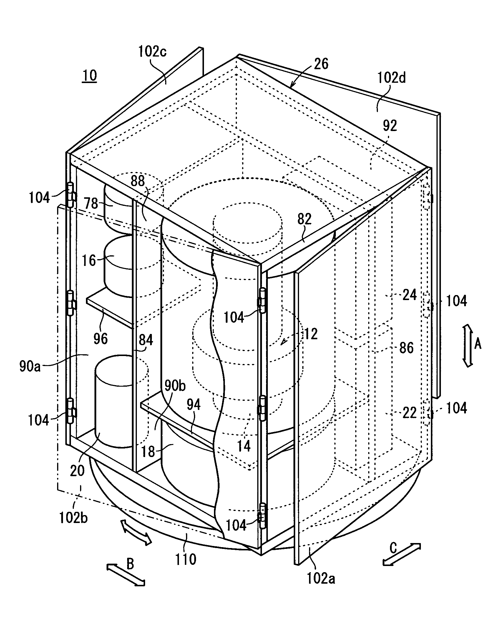
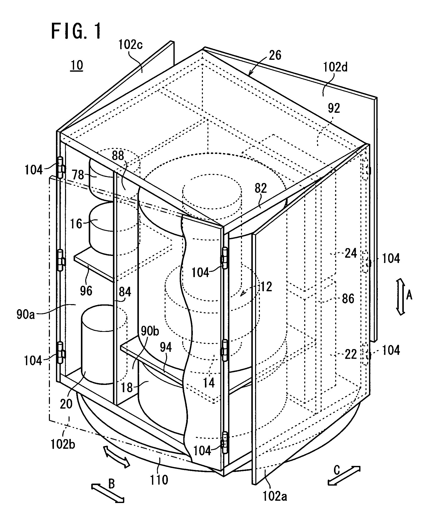
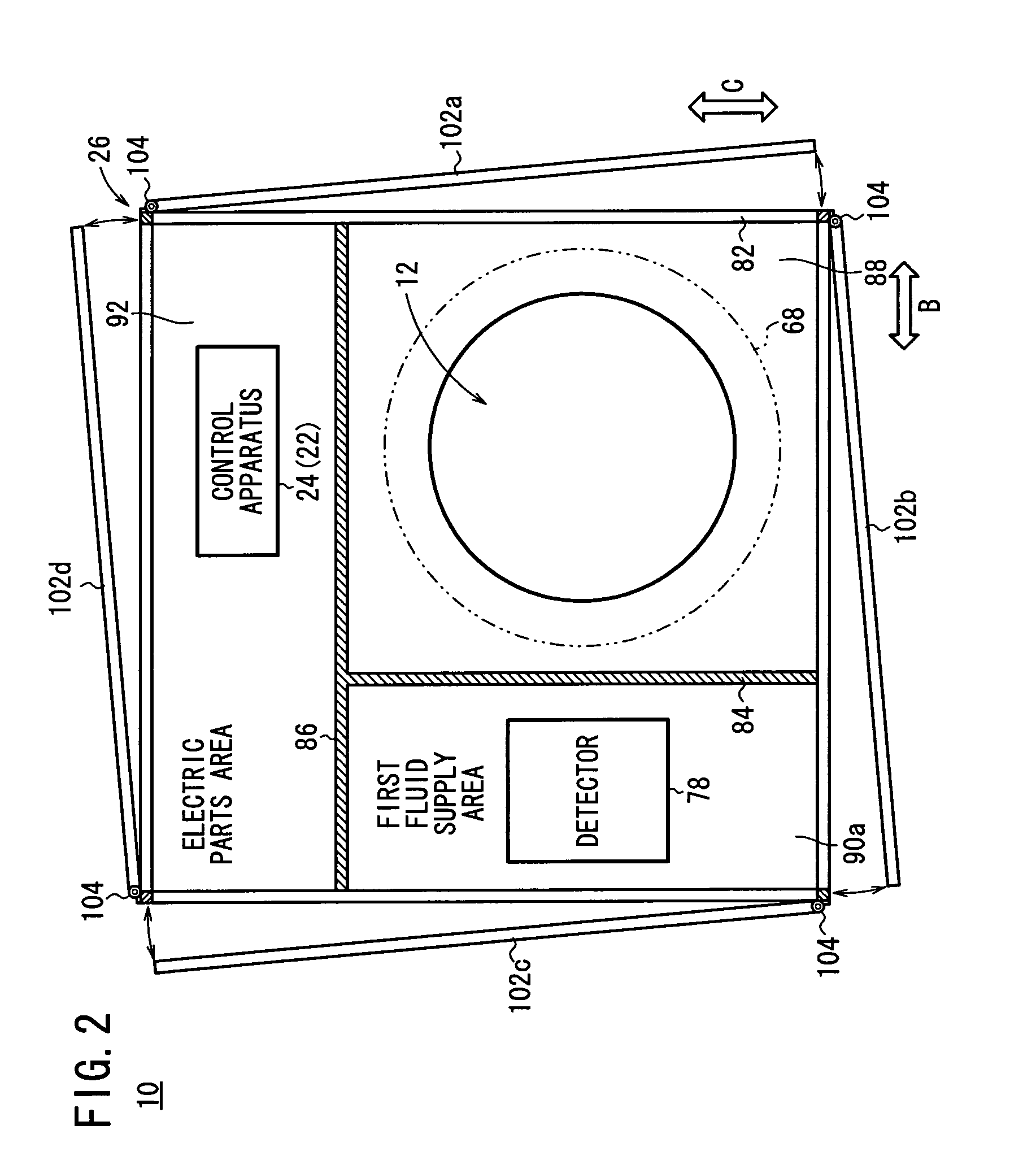
[0031]FIG. 1 is a perspective view schematically showing a fuel cell system 10 according to the present invention. FIG. 2 is a plan view showing the fuel cell system 10, FIG. 3 is a front view showing the fuel cell system 10, and FIG. 4 is a circuit diagram showing the fuel cell system 10.

[0032]The fuel cell system 10 is used in various applications, including stationary and mobile applications. For example, the fuel cell system 10 is mounted on a vehicle. The fuel cell system 10 includes a fuel cell module 12 for generating electricity by electrochemical reactions of a fuel gas (hydrogen gas) and an oxygen-containing gas (air), a combustor 14 for raising the temperature of the fuel cell module 12, a fuel gas supply apparatus (including a fuel gas pump) 16 for supplying the fuel gas to the fuel cell module 12, an oxygen-containing gas supply apparatus (including an air pump) 18 for supplying an oxygen-containing gas to the fuel cell module 12, a water supply apparatus (including a w...

second embodiment

[0079]Further, in the second embodiment, for example, at the time of carrying out the safety checking operation in the module area 88, by opening the first module area door 124a and / or the second module area door 124b, only the module area 88 is opened to the outside. In particular, when the safety checking operation is carried out immediately after operation of the fuel cell system 120 is stopped, the hot fluid in the module area 88 is not diffused to the electric parts area 92, the first fluid supply area 90a, the second fluid supply area 90b or the like.

[0080]Further, at the time of carrying out the maintenance operation for the first fluid supply area 90a by opening the first fluid supply area door 126, only the first fluid supply area 90a is opened to the outside. In the structure, heat transfer or fluid diffusion does not occur between the first fluid supply area 90a and the electric parts area 92. Thus, it is possible to carry out the safety checking operation and the mainten...

third embodiment

[0081]FIG. 8 is a plan view showing a fuel cell system 130 according to the present invention.

[0082]The fuel cell system 130 includes a casing 132 having a rectangular shape in a plan view. The space in the casing 132 is divided into the module area 88, the first fluid supply area 90a, and the electric parts area 92 by a first vertical partition plate 134 and a second vertical partition plate 136. The first vertical partition plate 134 is longer than the second vertical partition plate 136. In the structure, the volume of the first fluid supply area 90a is larger than the volume of the electric parts area 92.

[0083]A first door 138a, a second door 138b, a third door 138c, and a fourth door 138d are provided corresponding to respective side surfaces of the casing 132. The first door 138a partially opens and closes the module area 88, the second fluid supply area 90b and the electric parts area 92 all together. The second door 138b partially opens and closes the module area 88, the sec...


PUM

PropertyMeasurementUnit
temperatureaaaaaaaaaa
poweraaaaaaaaaa

Abstract

A casing of a fuel cell system is divided into a module area, a first fluid supply area, a second fluid supply area, and an electric parts area. The first fluid supply area is provided on a first side surface of the module area, and an electric parts area is provided on a second side surface of the module area. The second fluid supply area is provided under a bottom surface of the module area. A fuel cell module and a combustor are provided in the module area.

Description

RELATED APPLICATIONS[0001]This application is a 35 U.S.C. 371 national stage filing of International Application No. PCT / JP2008 / 052910, filed Feb. 14, 2008, which claims priority to Japanese Patent Application No. 2007-075141 and Japanese Patent Application No. 2007-075164, both filed on Mar. 22, 2007 in Japan. The contents of the aforementioned applications are hereby incorporated by reference.TECHNICAL FIELD[0002]The present invention relates to a fuel cell system including a casing containing a fuel cell module, a combustor, a fuel gas supply apparatus, an oxygen-containing gas supply apparatus, a water supply apparatus, a power conversion apparatus, and a control apparatus.BACKGROUND ART[0003]Typically, a solid oxide fuel cell (SOFC) employs an electrolyte of ion-conductive solid oxide such as stabilized zirconia. The electrolyte is interposed between an anode and a cathode to form an electrolyte electrode assembly. The electrolyte electrode assembly is interposed between separa...

Claims


Application Information

Patent Timeline
Patent Type & Authority Patents(United States)
IPC IPC(8): H01M8/24
CPCH01M8/04007H01M8/04126H01M8/0444H01M8/04679H01M8/04686H01M8/04731H01M8/0494H01M8/04955H01M8/2475H01M8/0612H01M8/12Y02E60/50
Inventor OGAWA, TETSUYAYAMAMOTO, JUNMIYAZAKI, TOMIONAGATANI, SHUJI
Owner HONDA MOTOR CO LTD
Why Eureka
Try Eureka