Eureka AIR delivers breakthrough ideas for toughest innovation challenges, trusted by R&D personnel around the world.

Liquid-gas phase reactor system

a reactor system and liquid gas technology, applied in the direction of rotary stirring mixers, transportation and packaging, preparation of carboxylic compounds, etc., can solve the problems of wall fouling, condenser inlet plugging, and conventional slinger designs providing only a modest improvemen

Inactive Publication Date: 2011-06-16
PIRAS LUCIANO +3
View PDF5 Cites 21 Cited by
  • Summary
  • Abstract
  • Description
  • Claims
  • Application Information

AI Technical Summary

Benefits of technology

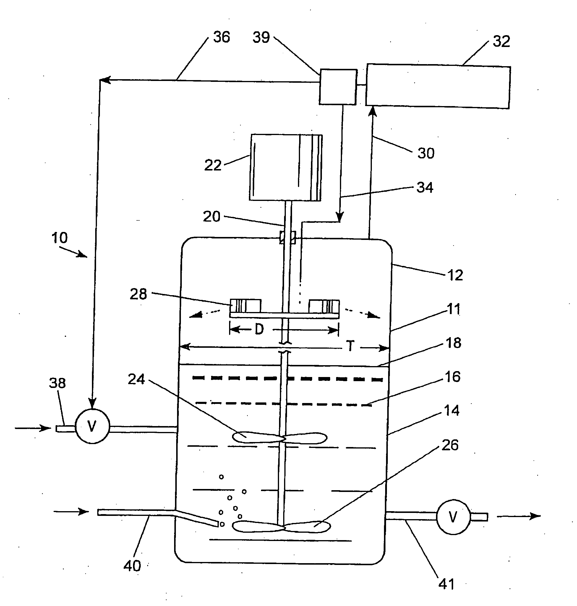
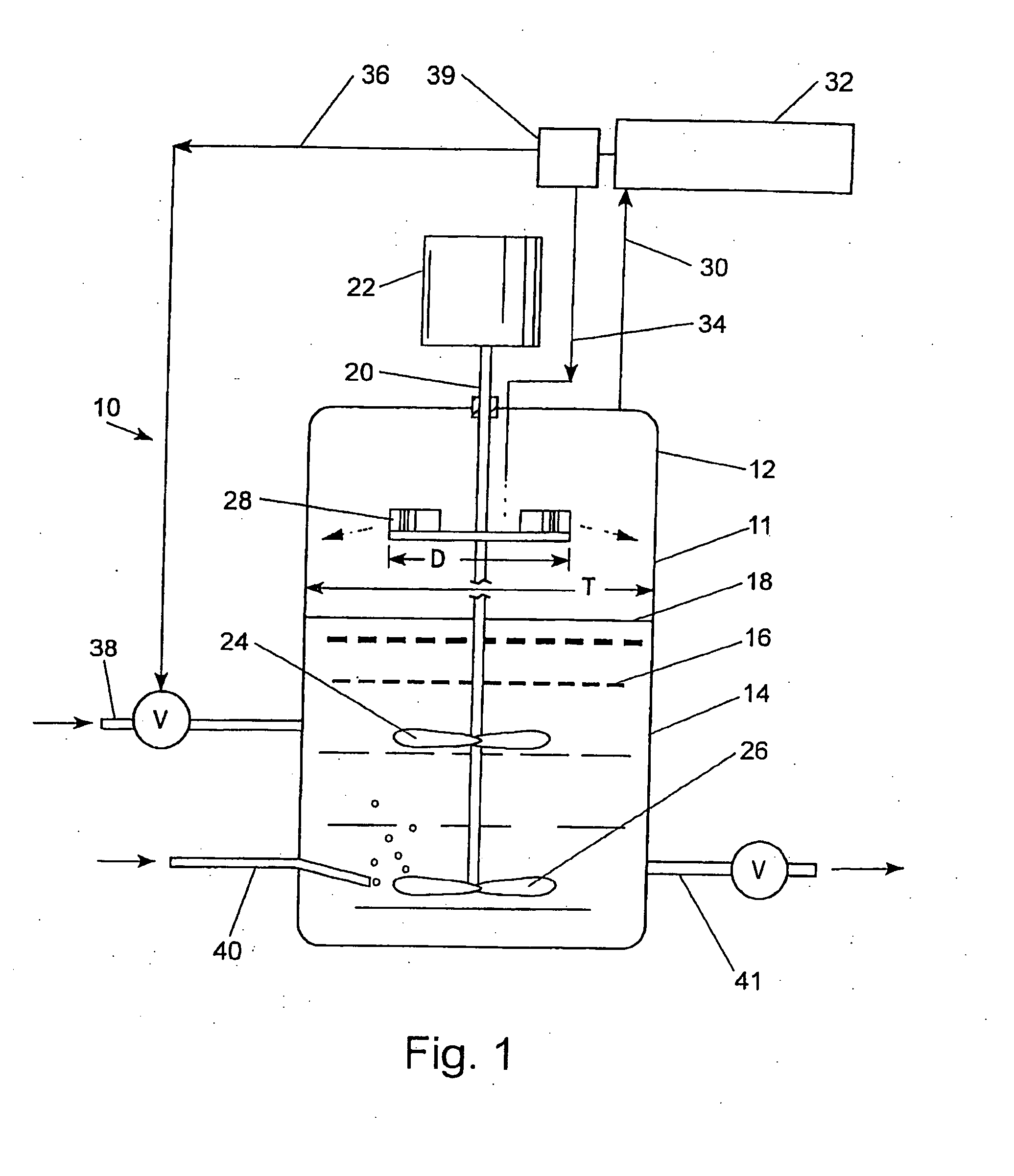
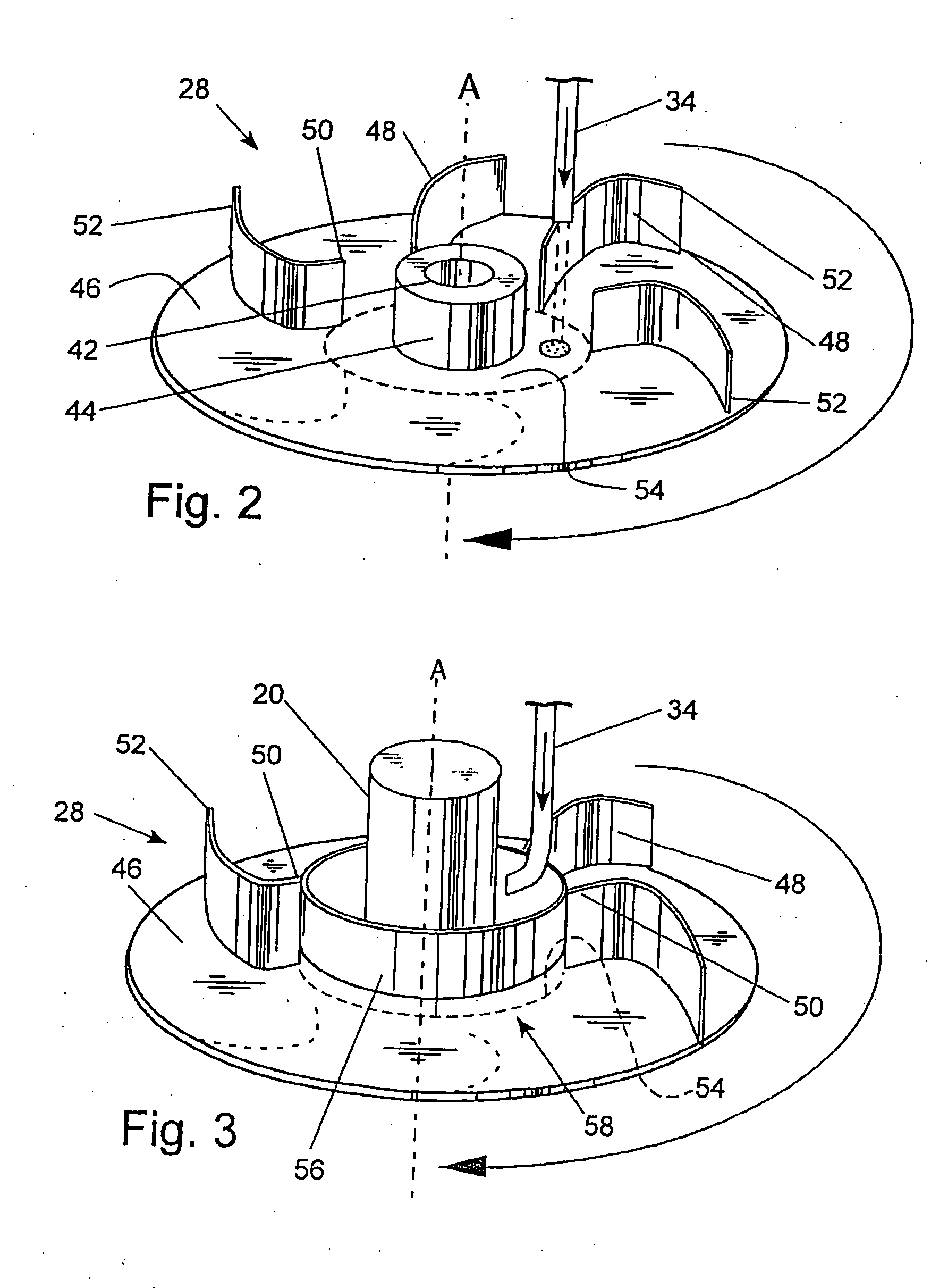
[0008]The use of a slinger to distribute condensate back to the reaction vessel can reduce both wall fouling and condenser plugging; however, conventional slinger designs provide only a modest improvement. For example, a conventional slinger used in such applications comprises a rotating, flat circular disk with a plurality of vertically raised, straight vanes extending radially outward from a center hub of the disk to its outer periphery. The slinger is located in the upper “head space” section of the vessel. Condensate is returned to the vessel via a conduit located above the rotating slinger. Condensate is fed onto the slinger where it is subsequently “slung” or distributed radially outward about the vessel. One shortcoming of this slinger is that the majority of condensate is distributed only over a limited cross-section of vessel with little condensate actually reaching the reactor walls. A second shortcoming is that liquid tends to be distributed in large droplets rather than finely divided droplets. Consequently, such systems experience wall fouling, condenser plugging, and poor mixing of condensate with the liquid phase reaction medium. Moreover, the present inventors have found that the aforementioned slinger is less effective at dissipating heat generated by exothermic reactions as compared with returning condensate to the vessel via a liquid inlet at a location below the liquid level, (e.g. with incoming fresh liquid reaction medium). For example, with the exothermic oxidation of aromatic alkyls, much of the heat generated by the reaction is concentrated in the middle section of the liquid reaction medium. These “hot spots” can lead to undesired reactions, consumption of solvent and increased vapor generation—all of which contribute to higher operating costs and lower efficiency. Additional studies by the present inventors have also demonstrated that the use of such a slinger provides less effective mixing of condensate with the liquid phase reaction medium, as compared with returning condensate via a liquid feed line at a point below the liquid level in the vessel—such as with the feed line used for introducing fresh liquid reaction medium.

Problems solved by technology

However, crystals can build-up on the walls of the reaction vessel (“wall fouling”) and can be entrained along with other solid debris in rising vapor which can lead to plugging of the condenser inlets (“condenser plugging”).
The use of a slinger to distribute condensate back to the reaction vessel can reduce both wall fouling and condenser plugging; however, conventional slinger designs provide only a modest improvement.
Consequently, such systems experience wall fouling, condenser plugging, and poor mixing of condensate with the liquid phase reaction medium.
Moreover, the present inventors have found that the aforementioned slinger is less effective at dissipating heat generated by exothermic reactions as compared with returning condensate to the vessel via a liquid inlet at a location below the liquid level, (e.g. with incoming fresh liquid reaction medium).
These “hot spots” can lead to undesired reactions, consumption of solvent and increased vapor generation—all of which contribute to higher operating costs and lower efficiency.

Method used


Image

  • Liquid-gas phase reactor system
  • Liquid-gas phase reactor system
  • Liquid-gas phase reactor system

Examples


Embodiment Construction

[0014]The present invention includes a liquid-gas phase reactor system and a method for oxidizing an organic reactant within a liquid-gas phase reactor system. The reactor system includes a reaction vessel, also referred herein as simply “vessel” or “reactor”. The vessel itself is not particularly critical to the invention and may comprise many boiling-type reactor configurations. As with most reaction systems, the nature of the chemical process will dictate the configuration and construction materials of the vessel and auxiliary equipment. For example, stainless steel or titanium materials are often used with highly corrosive chemical processes whereas carbon-based steels may be applicable for non-corrosive environments. For most applications, the vessel includes a circular cross-section such as a vertically aligned cylinder with an upper section corresponding to the head space region and a lower section corresponding to the liquid level of the liquid phase reaction medium within t...


PUM


Abstract

A liquid-gas phase reactor system including a slinger located in an upper section (headspace region) of a reaction vessel. The slinger comprises an upper horizontal surface including a plurality of vertically raised vanes extending radially outward along a curved path which effectively distribute liquid about the reactor vessel. A method for conducting an oxidation reaction using a liquid-gas phase reactor system is also disclosed. The disclosed reactor system and method have a broad range of applications but are particularly suited for the production of terephthalic acid.

Description

CROSS-REFERENCE TO RELATED APPLICATION[0001]This application claims the benefit of U.S. Provisional Application No. 60 / 846,783, filed Sep. 22, 2006.BACKGROUND OF THE INVENTION[0002](1) Field of the Invention[0003]The invention relates to liquid-gas phase reactor systems and methods for conducting liquid-gas phase reactions. Such reactions include both liquid and gas phase constituents within the same reaction vessel, such as the oxidation of aromatic alkyls (e.g. p-xylene) within a liquid phase reaction medium.[0004](2) Description of the Related Art[0005]Liquid-gas phase reactor systems are well known in the art and typically comprise a reaction vessel with optional auxiliary equipment. Reaction vessels including agitation devices are sometimes also referred to as “stirred tank reactors” or simply “STR” and those including oxygen-containing gas spargers as “liquid oxidation reactors” or “LOR” (see for example U.S. Pat. Nos. 5,108,662 and 5,536,875). Such reactor systems are commonl...

Claims


Application Information

Patent Timeline
IPC IPC(8): C07C51/265B01J7/02B01J19/00B01F25/74
CPCB01F5/221B01F7/00466B01F7/00641B01J2219/0013B01J19/0066B01J19/1806B01J2219/00105B01J10/002B01F25/741B01F27/1152B01F27/192C07C51/21B01J10/00
Inventor PIRAS, LUCIANOMONAGHEDDU, MARZIOGNAGNETTI, ANDREAKAR, KISHORE K.
Owner PIRAS LUCIANO
Why Eureka
Eureka Blog
Learn More