
Device for externally fixing bone fractures

a technology for fixing devices and bone fractures, applied in the field of devices for external fixing of bone fractures, can solve the problems of increasing the danger of post-operative infection, affecting the safety of patients, and the procedure can take a very long time, so as to achieve rapid and dimensionally stable stiffening of the device, reduce the risk of post-operative infection, and reduce the risk of fractures. the effect of simple reduction

Active Publication Date: 2011-06-16
LORENZ KAI UWE +3
View PDF13 Cites 23 Cited by
  • Summary
  • Abstract
  • Description
  • Claims
  • Application Information

AI Technical Summary

Benefits of technology

[0010]It is an object of the invention to make available a device that is of the kind mentioned at the outset and that does not have the abovementioned disadvantages or other disadvantages. In particular, such a device for the external fixation of bone fractures should permit simple reduction of a bone fracture by pins introduced into the bones, or the bone fragments, and a subsequent rapid and dimensionally stable stiffening of the device. A device according to the invention should preferably be able to be handled easily and with few maneuvers, even under stressful conditions. If the reduction is unsatisfactory, the device according to the invention should also be easy to unlock again in order to permit correction of the reduction and then renewed stiffening. A device according to the invention should also preferably be radioparent for the most part, in order to allow the reduction to be monitored. In addition, it should preferably also be able to be used in a nuclear magnetic resonance scanner.
[0011]A further object of the invention is to make available a method for the fixation of bone fractures that permits rapid and simple initial treatment of fractures but can also be used for definitive osteosynthesis.
[0014]In a preferred variant of a device according to the invention, the tensile force element is already pretensioned with a certain tensile force in the unlocked state, with the result that, when the device is fitted in place, it holds provisionally on the pins, and yet the fixator device can still easily be brought to the desired shape by the operator when the fracture is reduced. After being let go, the device according to the invention maintains the shape provisionally.
[0015]All suitable materials, in particular metals and fiber-reinforced plastics, can be used both for the tensile force element and also for the joint elements. However, for the tensile force elements, it is preferable to use wires, cords, cables or particularly preferably fiber bundles (also referred to below simply as bundles) made of metal, carbon fiber, or of other suitable plastics or combinations of the aforementioned materials which, with a low weight, are able to take up very high tensile forces, without deforming even over a period of months. For the ball joint elements, fiber-reinforced polymer materials are preferably used in order to ensure a high degree of mechanical stability with at the same time a low weight. Such a choice of the materials also has the advantage that the device according to the invention is radioparent and also has no metal parts that would cause artefacts in a nuclear magnetic resonance scanner or would prohibit its use in the magnetic field of the nuclear magnetic resonance scanner.

Problems solved by technology

In the case of open fractures, it may also be necessary to stabilize the fracture with an external fixator, since definitive primary treatment of the fracture by means of a plate, screw or nail would increase the danger of a post-operative infection.
The fitting of an external fixator is often very time-consuming in the known models, since many screws generally have to be tightened after the fracture has been reduced, and, if the position is unsatisfactory, they have to be undone again to allow correction and then tightened anew.
If several corrections of position are needed, this procedure can take a very long time.
For the reasons set out above, this is not possible with the previous fixator systems.
Some designs of external fixators also make anatomical adjustment of the bone fracture fragments difficult, since four or more bone pins have to be oriented on a straight line, which can be made difficult or impossible on account of the pin position.
Moreover, the structure of the known fixator systems with bars and tubes is often large and bulky.
Moreover, after the elements have been strung onto the tensioning cable, a fine adjustment to the position of the pins is no longer possible.
However, since the position of the holding devices on the fixator is predefined, or the fixator has to be correspondingly prepared when being assembled, said device is suitable in particular for planned operations, but less so for initial treatment under time constraints.
However, in this embodiment, the overall shape cannot be adapted so quickly, because a large number of locks first have to be released.

Method used


Image

  • Device for externally fixing bone fractures
  • Device for externally fixing bone fractures
  • Device for externally fixing bone fractures

Examples


Embodiment Construction

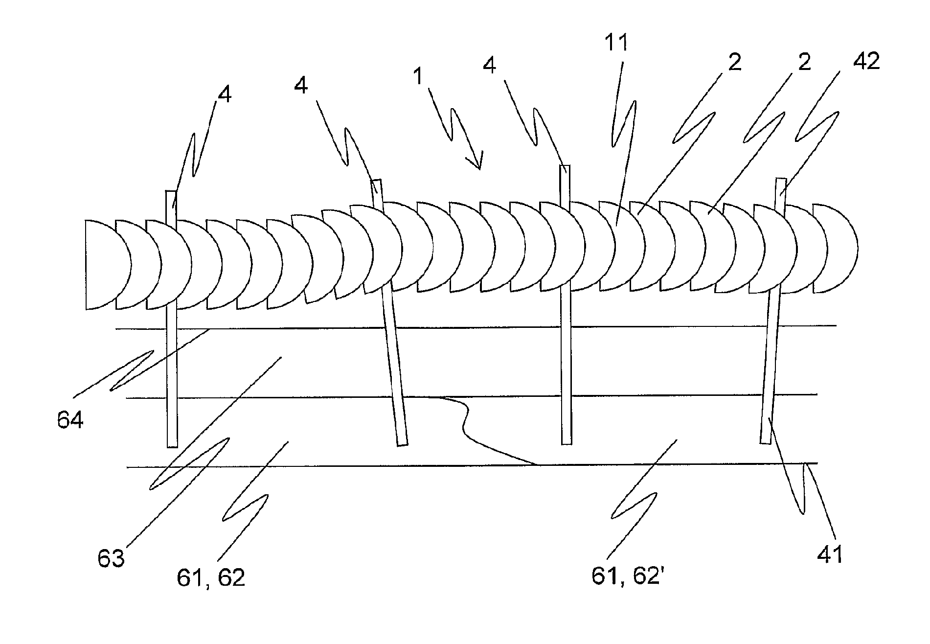
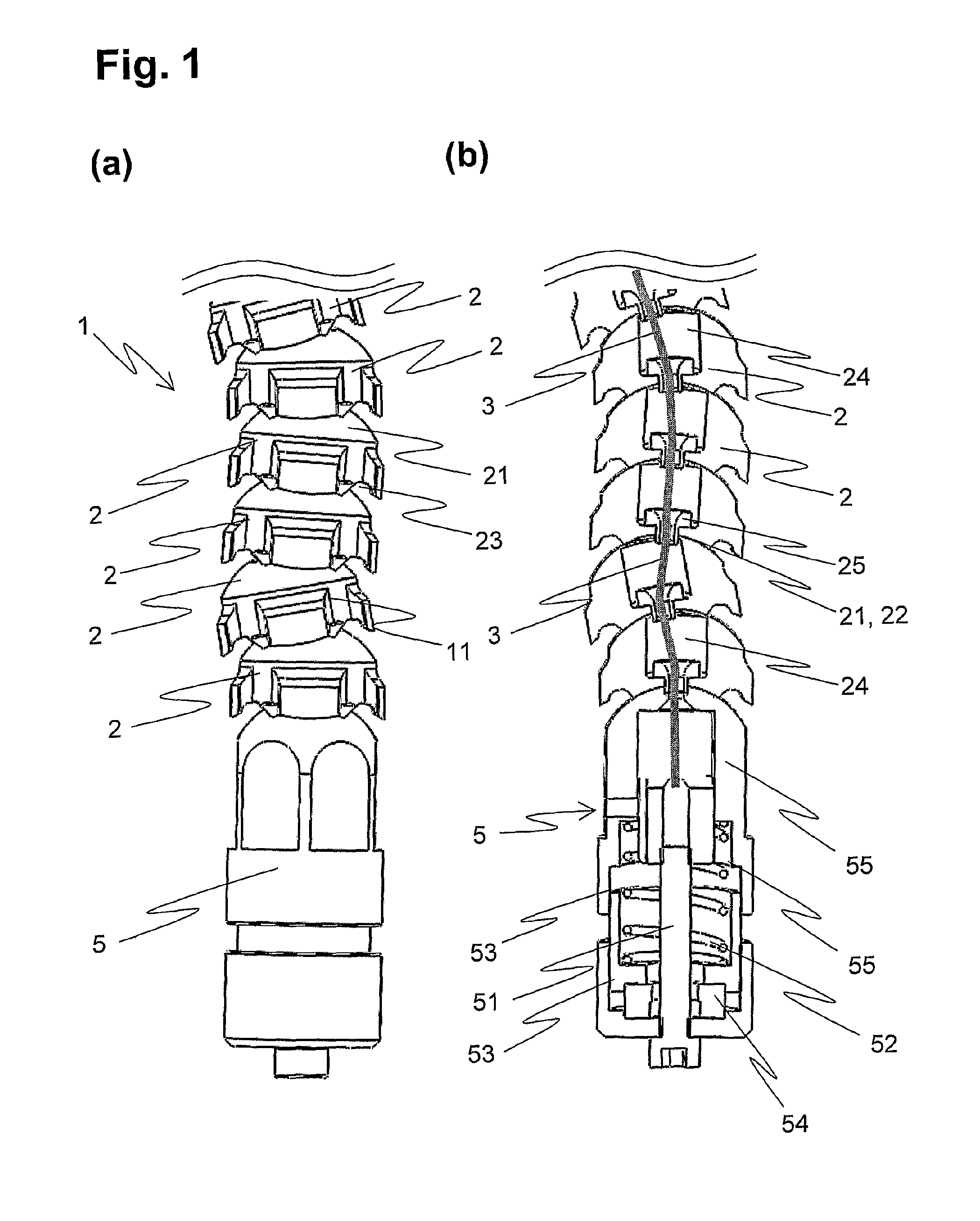
[0027]A possible embodiment of a device 1 according to the invention for the external fixation of bone fractures is shown in FIG. 1, (a) in side view, and (b) in a longitudinal section.

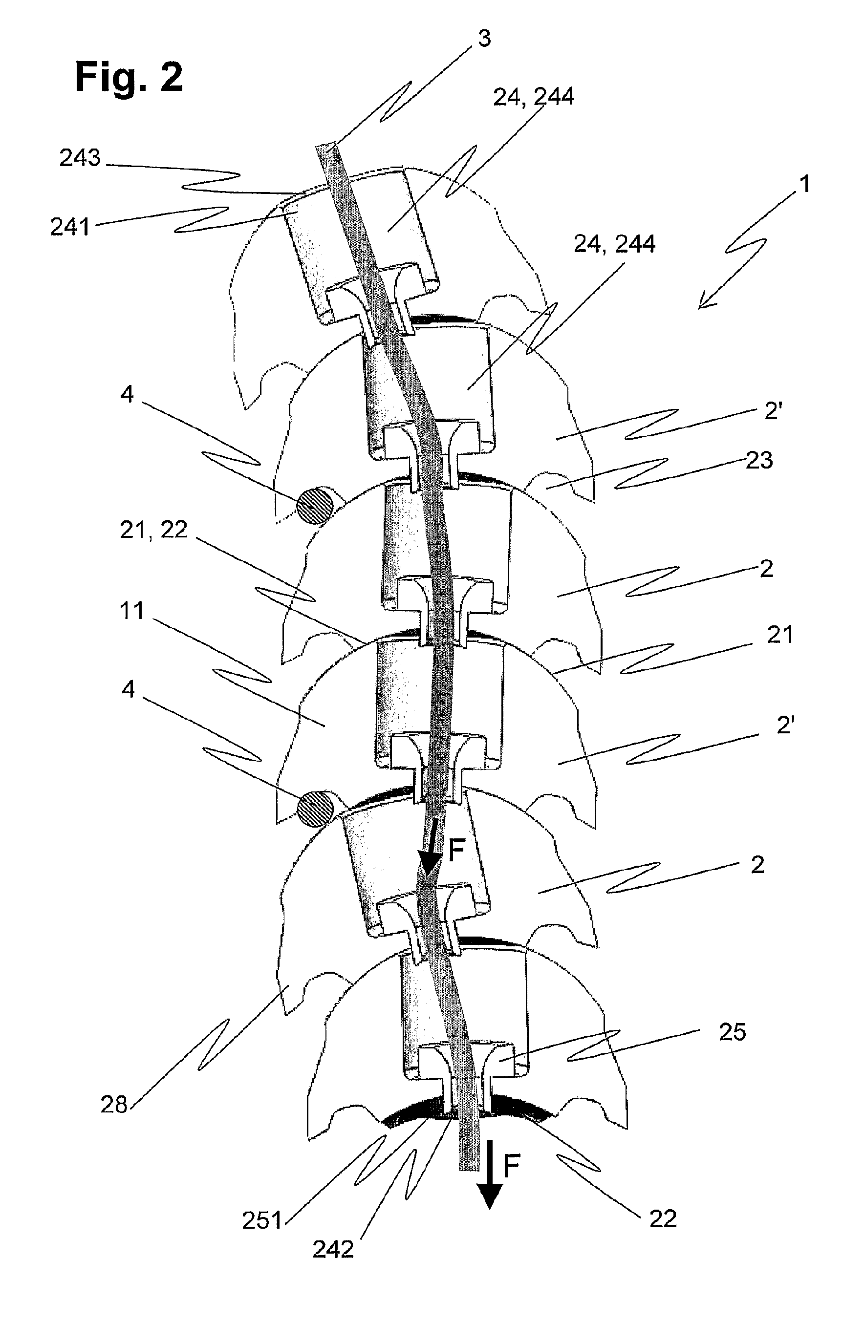
[0028]The rear end of the support 11 of the device 1 is shown, comprising the six rearmost joint elements 2 and, at the end, a tensioning device 5 for generating the tensile force needed for stiffening the device 1. The tensile force element 3 running along the entire length of the support 11 extends from the tensioning element 5 through the longitudinal passages 24 of the joint elements 2 and finishes, at a front end (not shown) of the support, in an abutment which takes up an applied tensile force and transmits this to the joint elements 2. The tensile force element is preferably designed as a fiber bundle which, with the least possible thickness, has the greatest possible tensile strength. Suitable bundles for this purpose are, for example, wire bundles, carbon fiber bundles, or bundles made of oth...


PUM


Abstract

A device (1) according to the invention for externally fixing broken bones (62, 62′) of a patient, particularly the extremities, comprises a support (11) composed of a plurality of joint elements (2, 2) that are stringed together, wherein said support can be disposed outside the body of the patient. The proximal ends (41) of at least two percutaneously disposed pins (4) are anchored in the bone tissue (61) of the patient, and the distal ends (42) are fixed to the support (11). The joint elements (2) are stringed on a central tensile force element (3), and in each case two adjoining joint socket (22). The individual ball joints, and thus the support (11), can be fixed in a reversible frictionally engaged manner by applying a tensile force of the central tensile force element (3). The joint elements (2, 2′) in turn are designed such that a pin (4) can be fastened to the support (11) in a clamping and / or frictionally engaged manner by applying the tensile force of the central tensile force element (3).

Description

TECHNICAL FIELD[0001]The invention relates to a device for the external fixation of bone fractures, to joint elements for such a device, and to a method for the fixation of bone fractures, in accordance with the preambles of the independent claims.PRIOR ART[0002]An external fixator is a device which is mounted outside the body and which is fixed to the bone via threaded metal rods called pins, for the purpose of external fixation of bone fractures of a patient, and is generally used on open fractures with soft-tissue damage or in cases of multiple injuries. In emergency operations on patients with multiple injuries, it is often necessary to defer the definitive treatment of bone fractures of the extremities, for example of the upper leg or lower leg, until other life-threatening injuries have been treated, so as not to put the life of the patient at risk. After a first reduction of the fracture, the latter is provisionally stabilized using an outer frame, the external fixator. In th...

Claims


Application Information

Patent Timeline
IPC IPC(8): A61B17/00
CPCA61B17/6408A61B2017/606A61B17/6416
Inventor LORENZ, KAI-UWEDURST, HEIKO
Owner LORENZ KAI UWE
Learn More