Trocar device
What is Al technical title?
Al technical title is built by PatSnap Al team. It summarizes the technical point description of the patent document.
a technology which is applied in the field of cannula and trocar device, can solve the problems of affecting the treatment effect, etc., and achieving the effect of overcoming the resistance of the abdominal wall with unpredictable force, and avoiding damag
Active Publication Date: 2011-06-16
COVIDIEN LP
View PDF15 Cites 1 Cited by
Summary
Abstract
Description
Claims
Application Information
AI Technical Summary
This helps you quickly interpret patents by identifying the three key elements:
Problems solved by technology
Method used
Benefits of technology
Problems solved by technology
In this case, damage could occur.
In fact, damage does occur in a certain number of surgical cases annually.
In addition, an unpredictable force is generally required to overcome the resistance of the tissue of the abdominal wall.
Since the force is variable and unique to the given tissue composition, the user cannot accurately predict how much force may be required on any given insertion.
A further disadvantage of the above-described instruments and systems is the lack of any feedback to the operator as to when then instrument has actually entered into the abdominal cavity.
This can lead to damage of vital organs and misuse of the instrument.
A further disadvantage of the above-described instruments and systems is that such instruments and systems typically require manual manipulation and operation.
When excessive force is used, damage to vital organs can occur.
A further disadvantage of the above-described instruments and systems is that such instruments and systems typically utilize a diamond-pointed-like trocar which penetrates the abdomen like a nail penetrates wood when hammered.
This trocar placement method does not account for the potential variation in tissue thickness, tissue variability within the abdominal wall, and does not allow for counter-traction which would provide the users with the need to apply less force.
Method used
Image
Click on the blue label to locate the original text in one second.
Reading with bidirectional positioning of images and text.
Examples
Embodiment Construction
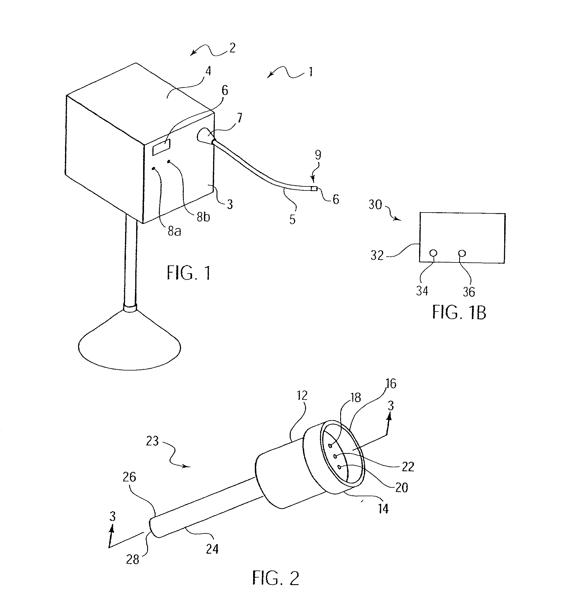
[0032]Those skilled in the art will gain an appreciation of the present invention from a reading of the following description when viewed in conjunction with the accompanying drawings of FIGS. 1-14E, inclusive. The individual reference characters designate the same or similar elements throughout the several views.
[0033]Referring to FIG. 1, a perspective view of an electro-mechanical driver device 1 according to one embodiment of the present invention is shown. Electro-mechanical driver device 1 may include, for example, a remote power console 2, which includes a housing 4 having a front panel 3. Mounted on front panel 3 are a display device 6 and indicators 8a, 8b. A flexible shaft 5 may extend from housing 4 and may be detachably secured thereto via a first coupling 7. The distal end 9 of flexible shaft 5 may include a second coupling 6 adapted to detachably secure a surgical instrument or attachment to the distal end 9 of flexible shaft 5. The surgical instrument or attachment may...
PUM
Abstract
A surgical device is described. The surgical device may comprise a rotatable cutter configured to cut tissue for insertion of a cannula, and a first driver configured to be driven by a motor arrangement and to rotate the cutter. The surgical device may further include, for example, the cannula, at least one of the rotatable cutter and the first driver being disposed in a bore of the cannula. In one embodiment, the rotatable cutter may include an auger having a cutting thread. In another embodiment, the rotatable cutter may include a disk-shaped blade.
Description
RELATED U.S. APPLICATION DATA[0001]This application relates to U.S. patent application Ser. No. 09 / 324,452, filed on Jun. 2, 1999, entitled “Electromechanical Driver Device For Use With Anastomosing, Stapling, and Resecting instruments,” U.S. patent application Ser. No. 09 / 510,923, filed on Feb. 22, 2000, entitled “A Carriage Assembly For Controlling a Steering Wire Mechanism Within a Flexible Shaft,” U.S. patent application Ser. No. 09 / 723,715, filed on Nov. 28, 2000, entitled “Electro-Mechanical Surgical Device,” U.S. Provisional Patent Application Ser. No. 60 / 275,869, filed on Mar. 14, 2001, entitled “Trocar Device,” U.S. patent application Ser. No. 09 / 887,789, filed on Jun. 22, 2001, entitled “Electro-Mechanical Surgical Device,” U.S. Pat. No. 09 / 836,781, filed on Apr. 17, 2001, entitled “Electro-Mechanical Surgical Device”, and U.S. Provisional Patent Application No. 60 / 337,544, filed on Dec. 4, 2001, entitled “Calibration of a Surgical Instrument,” each of which is expressly i...
Claims
Application Information
Patent Timeline
Application Date:The date an application was filed.
Publication Date:The date a patent or application was officially published.
First Publication Date:The earliest publication date of a patent with the same application number.
Issue Date:Publication date of the patent grant document.
PCT Entry Date:The Entry date of PCT National Phase.
Estimated Expiry Date:The statutory expiry date of a patent right according to the Patent Law, and it is the longest term of protection that the patent right can achieve without the termination of the patent right due to other reasons(Term extension factor has been taken into account ).
Invalid Date:Actual expiry date is based on effective date or publication date of legal transaction data of invalid patent.
Patent Type & Authority Applications(United States)