Special Treatment on Circular Ring Part of the OLED Bank Structure with Surface Evolver

Inactive Publication Date: 2011-06-16
KATEEVA
View PDF3 Cites 2 Cited by
  • Summary
  • Abstract
  • Description
  • Claims
  • Application Information

AI Technical Summary

Benefits of technology

[0008]An embodiment of the present invention may be a system or method for determining an equilibrium shape of

Problems solved by technology

Obtaining an optimum droplet interface when the substrate is not flat can be very difficult and is very dependent upon the initial guess.
For example, if the substrate includes a curved bank structure such as those found in OLED production can be very difficult.

Method used


Image

  • Special Treatment on Circular Ring Part of the OLED Bank Structure with Surface Evolver
  • Special Treatment on Circular Ring Part of the OLED Bank Structure with Surface Evolver
  • Special Treatment on Circular Ring Part of the OLED Bank Structure with Surface Evolver

Examples


example

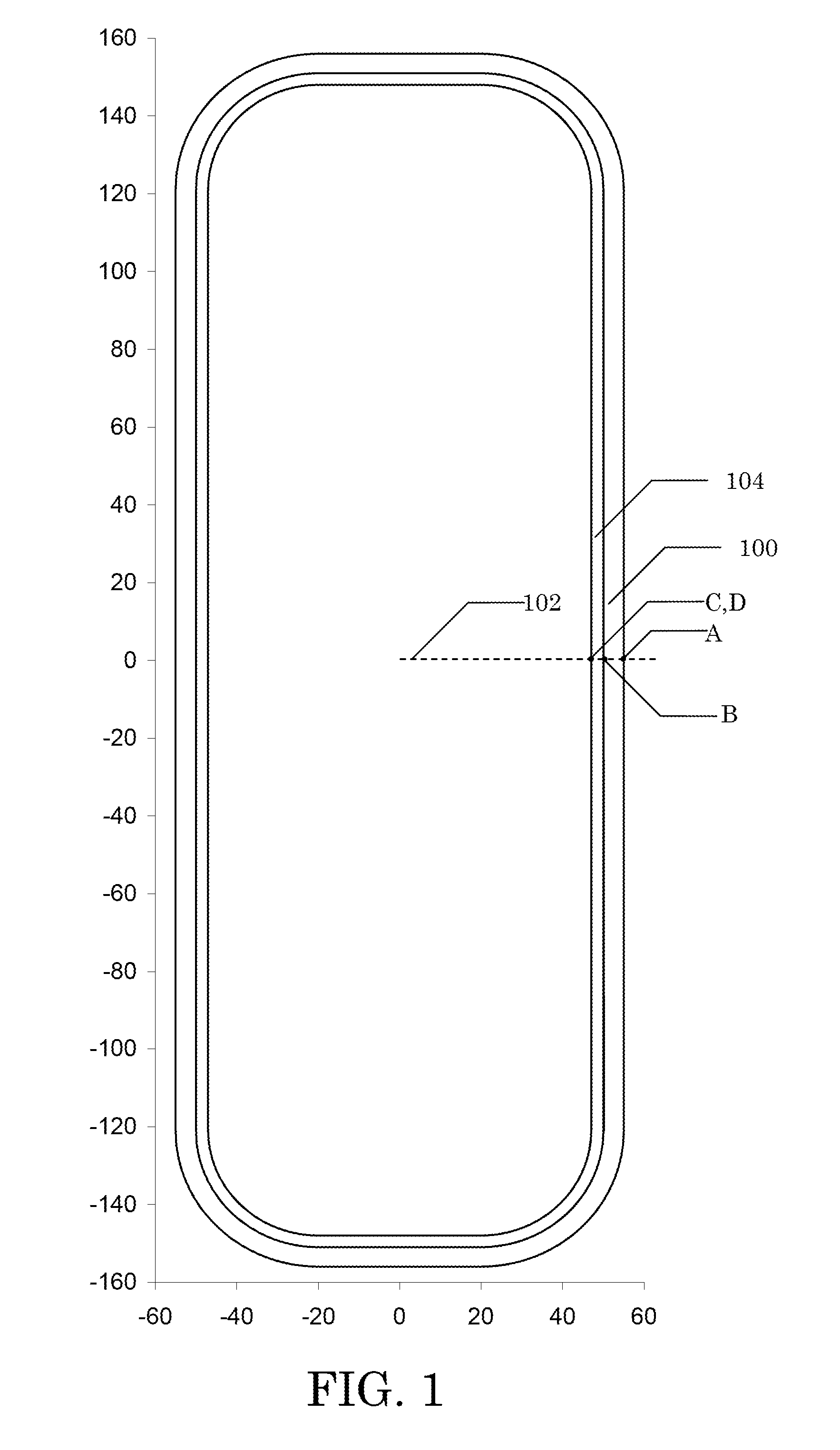
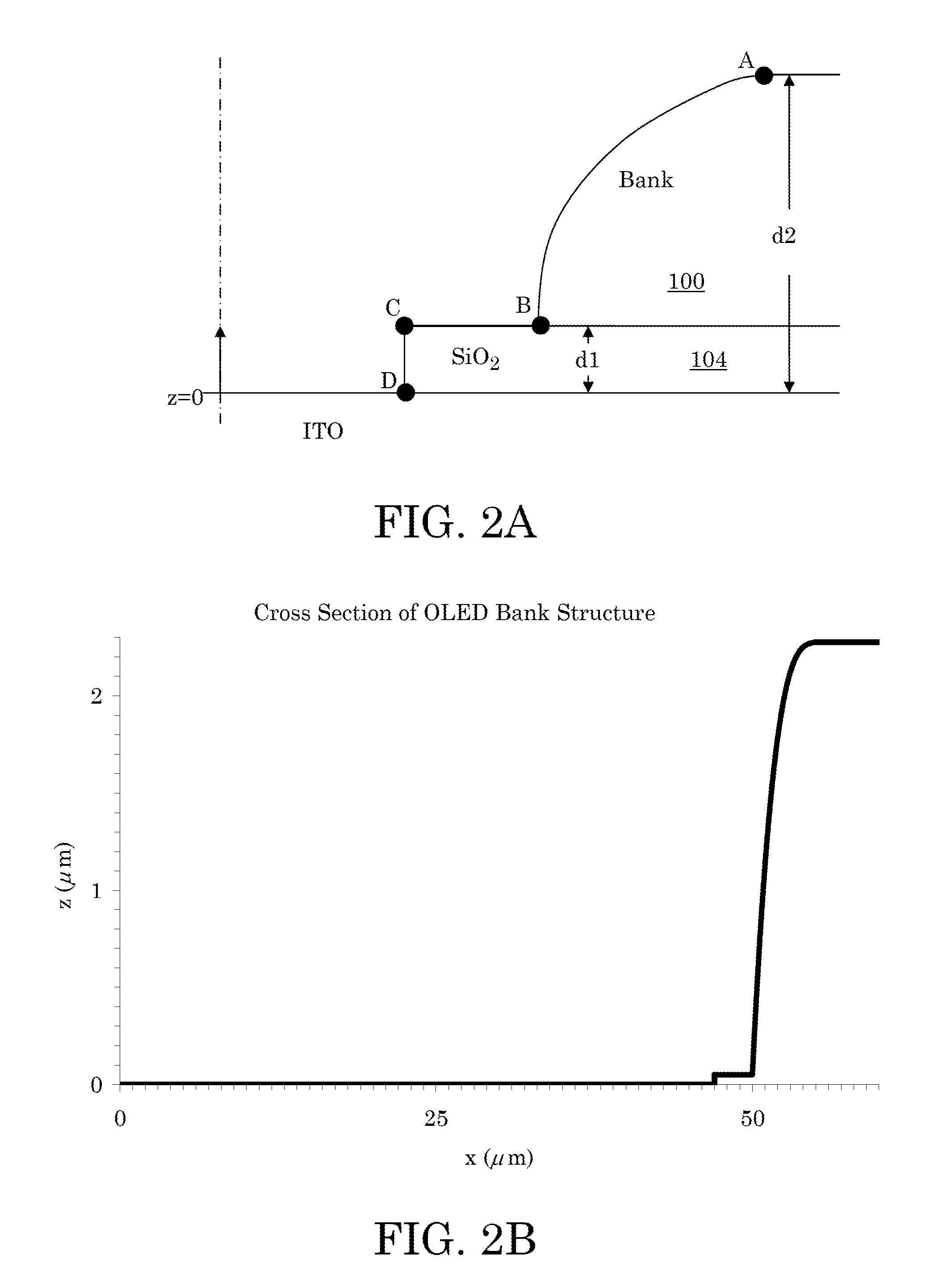
[0070]An embodiment of the present invention may be used to describe a surface 900 that includes concave convex face as illustrated in FIG. 9A. FIG. 9A is an illustration of OLED bank structure in FIG. 1 in which the nodes that initially define it are shown as black dots. The profile of the surface 800 may follow the one illustrated in FIGS. 2A-B. Note that FIG. 9A is not drawn to scale.

[0071]The origin may be set at the center of the bottom surface as illustrated in FIG. 9A as the point O. A length measurement Laxis (e.g. 121 μm) may represent half the length of a long side wall of an OLED bank structure be simulated. A length measurement Saxis (e.g. 20 μm) may represent half the length of short side wall of the OLED bank structure being simulated. A radius rad1 (e.g. 27 μm) may represent a corner radius at an intersection of ITO layer and the thin film SiO2 layer 104. A radius rad2 (e.g. 30 μm) may represent a corner radius at an intersection of the thin film SiO2 layer 104 and th...


PUM


Abstract

Systems and methods for representing a surface with faces. Defining a face with inner and outer concave constraint lines. Representing the face with five initial vertices spread equidistant on each of the inner and outer concave constraint lines. Using a triangulation refinement method to transform the initial set of vertices into a first set of representative vertices.

Description

BACKGROUND[0001]1. Field of Invention[0002]The present invention is related to systems and methods for determining a surface profile of a droplet on a complex surface.[0003]2. Description of Related Art[0004]Applying inkjet technology to the industrial printing process can greatly improve its efficiency. Inkjet technology can be used to save energy, material, money, and it can also help improve the environment. Inkjet technology may be used in the manufacture of liquid crystal displays (LCD), thin film transistors (TFT), organic light emitting diodes (OLED), solar cells, micro-circuits, and other planar, layered, or 3-D structures. In the inkjet printing process, small droplets of a solution are deposited onto a target area.[0005]Once the droplet is deposited onto a substrate it takes on an initial equilibrium droplet shape. The droplet shape is defined by a droplet interface. The droplet interface represents the extant of the droplet within an environment. The droplet interface is ...

Claims


Application Information

Patent Timeline
IPC IPC(8): G06G7/48G06T17/00
CPCG06T17/20G06G7/48
Inventor ZHANG, JIE
Owner KATEEVA
Why Eureka
Try Eureka