Plasma lamp having tunable frequency dielectric waveguide with stabilized permittivity

Inactive Publication Date: 2011-06-23
LUXIM CORP
View PDF10 Cites 11 Cited by
  • Summary
  • Abstract
  • Description
  • Claims
  • Application Information

AI Technical Summary

Benefits of technology

In some examples, the orientation of the bulb allows a thicker bulb wall to be used while allowing light to be efficiently transmitted out of the bulb. In one example, the thickness of the side wall of the lamp is in the range of about 2 mm to 10 mm or any range subsumed therein. In some examples, the thicker

Problems solved by technology

Because electrodes are not used, they may ha

Method used


Image

  • Plasma lamp having tunable frequency dielectric waveguide with stabilized permittivity
  • Plasma lamp having tunable frequency dielectric waveguide with stabilized permittivity
  • Plasma lamp having tunable frequency dielectric waveguide with stabilized permittivity

Examples


Embodiment Construction

While the present invention is open to various modifications and alternative constructions, the example embodiments shown in the drawings will be described herein in detail. It is to be understood, however, there is no intention to limit the invention to the particular example forms disclosed. On the contrary, it is intended that the invention cover all modifications, equivalences and alternative constructions falling within the spirit and scope of the invention as expressed in the appended claims.

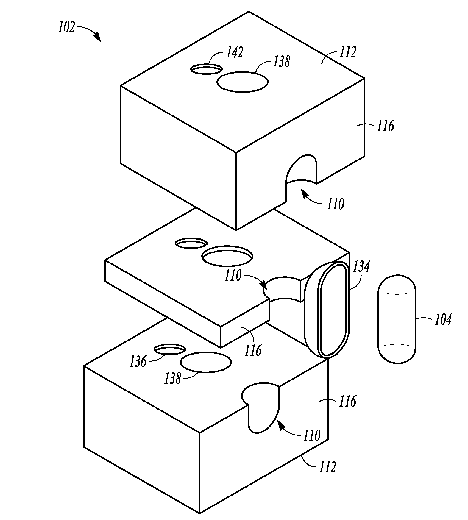
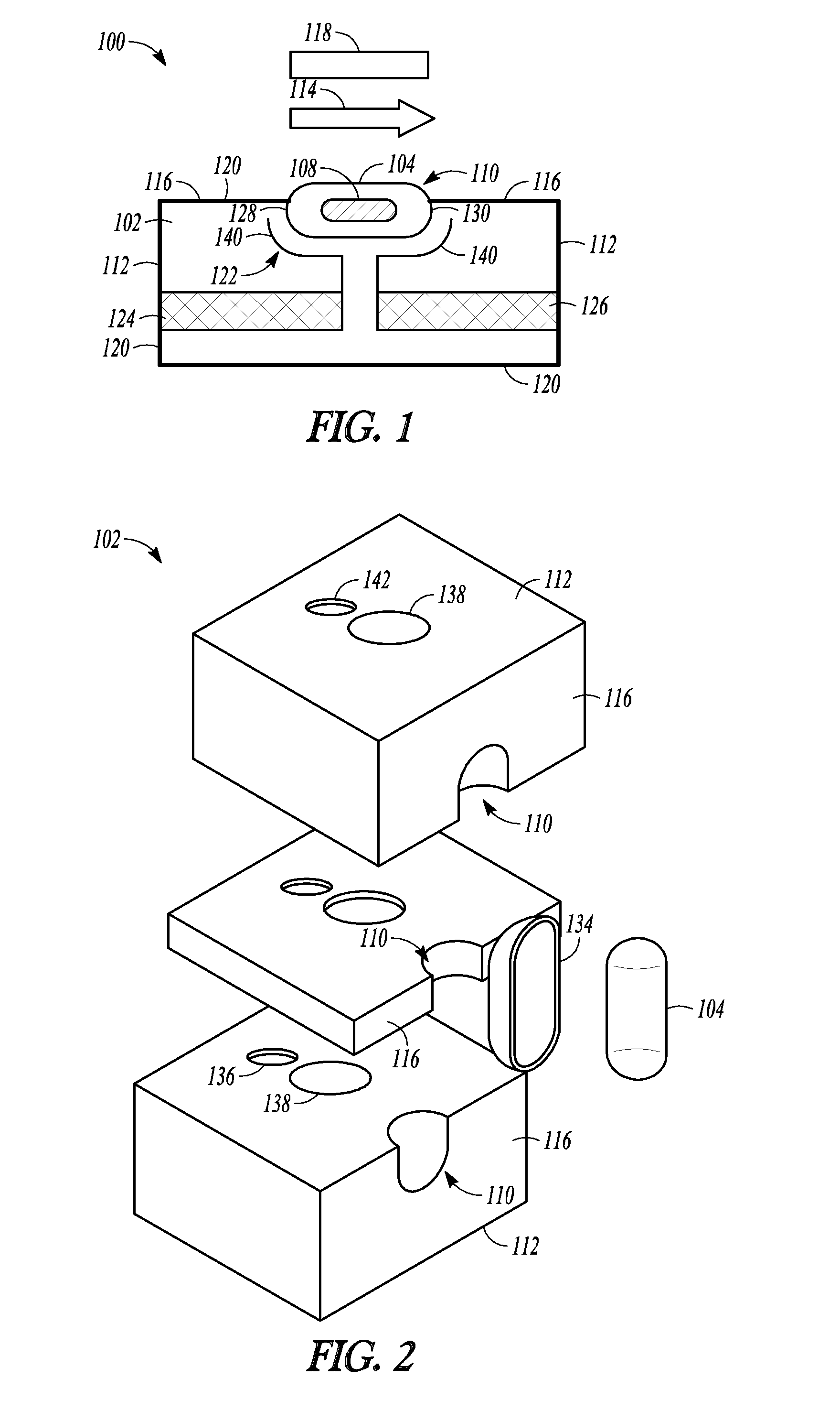
FIG. 1 is a cross-section and schematic view of a plasma lamp 100, according to an example embodiment. The plasma lamp 100 may have a lamp body 102 formed from one or more solid dielectric materials and a bulb 104 positioned adjacent to the lamp body 102. The bulb 104 contains a fill that is capable of forming a light emitting plasma. A lamp drive circuit (e.g., a lamp drive circuit 106 shown by way of example in FIG. 9) couples RF power into the lamp body 102 which, in turn, is coupled in...


PUM


Abstract

An electrodeless plasma lamp and method of generating light are described. The lamp may comprise a lamp body, a source of radio frequency (RF) power and a bulb. The lamp body may comprise a solid dielectric material and at least one conductive element within the solid dielectric material. The source of RF power is configured to provide RF power and an RF feed configured to radiate the RF power from the RF source into the lamp body. One or more tuning mechanisms allow tuning of the lamp body to a given resonant frequency. The bulb is positioned proximate the lamp body and contains a fill that forms a plasma when the RF power is coupled to the fill from the lamp body. The at least one conductive element is configured to concentrate an electric field proximate the bulb.

Description

FIELDThe field relates to systems and methods for generating light and, more particularly, to electrodeless plasma lamps.BACKGROUNDElectrodeless plasma lamps may be used to provide bright, white light sources. Because electrodes are not used, they may have longer useful lifetimes than other lamps. In many applications, it is desirable to have a lamp capable of high light collection efficiency. Collection efficiency can be expressed as the percentage of light that can be collected from a source into a given Etendue compared to the total light emitted by that source. High collection efficiency means that most of the power consumed by the lamp is going toward delivering light where it needs to be. In microwave energized electrodeless plasma lamps, the need for high collection efficiency is elevated due to the losses incurred by converting DC power to RF power. In many applications, it is also desirable to have a lamp with high luminous efficiency. Luminous efficiency can be expressed a...

Claims


Application Information

Patent Timeline
IPC IPC(8): H01J11/00
CPCY02B20/22H01J65/044Y02B20/00
Inventor HAFIDI, ABDESLAMO'HARE, DANDEVINCENTIS, MARC
Owner LUXIM CORP
Why Eureka
Try Eureka