Camera system and image processing method

a camera system and image processing technology, applied in the field of camera system and image processing method, can solve the problems of power consumption of transmission lines, plurality of expensive, and the need to construct expensive camera systems including transmission cables, and achieve the effect of high accuracy, efficient compression coding of image data, and high accuracy

Active Publication Date: 2011-06-23
SONY CORP
View PDF4 Cites 34 Cited by
  • Summary
  • Abstract
  • Description
  • Claims
  • Application Information

AI Technical Summary

Benefits of technology

[0011]A wavelet transform in particular can achieve a very high compression efficiency by subband division of an entire picture. However, the existing system separates the entire picture into separate pictures, and thus does not exert the inherently high compression efficiency of the wavelet transform.
[0015]In addition, Patent Document 1 discloses a technique for performing compression and recording without color separation into RGB full pixels. This technique compresses image data as it is without an increase in data rate due to color separation, and thus has an advantage of being able to control the data rate. However, details on how to compress image data are not clear. If image data is literally compressed as one image as it is in a Bayer arrangement, the level of each of RGB pixels differs in many natural images. Then, because adjacent pixels are differently painted into RGB, very large high-frequency components occur, and compression efficiency is not increased. In other words, very high compression noise is expected.
[0016]It is desirable to perform efficient compression coding of RAW data obtained from an image pickup element of a pixel arrangement in which pixel positions of at least one color of three primary colors are alternately shifted from each other in a horizontal direction or a vertical direction, and transmit an image from a camera section to a CCU section.
[0021]According to the present invention, even when pixel positions are alternately shifted from each other in a horizontal or vertical direction, subband division is performed with pixels of two upper and lower lines adjacent to each other or pixels of two left and right columns adjacent each other as a unit. Thus, by performing compression coding with the pixel positions remaining shifted from each other, efficient compression coding can be performed.
[0022]According to the present invention, the signal processing of the camera section can be performed with high accuracy and in real time because the camera section compresses image data (for example RAW data) and transmits the compressed data to the CCU section, and the CCU section decompresses the compressed data and thereby reproducing the image data. At this time, it is possible to perform efficient compression coding of image data obtained from an image pickup element of a pixel arrangement in which pixel positions of at least one color of three primary colors are alternately shifted from each other in a horizontal direction or a vertical direction.

Problems solved by technology

However, when RAW image data is transmitted in an uncompressed state, a transmission band is increased as compared with a case of RAW image data being compressed, and thus the power consumption of a transmission line is increased.
In addition, to secure a transmission band, a plurality of expensive transmission cables having a transmission rate of 10 Gbps need to be secured, and a very expensive camera system including the transmission cables needs to be constructed.
In addition, even when a case of compressing RAW image data as it is is assumed, details on a concrete method used to compress RAW image data are not clear, or compression efficiency is not increased.
Thus, the correlation between the separated images cannot be used, and compression efficiency is decreased.
However, the existing system separates the entire picture into separate pictures, and thus does not exert the inherently high compression efficiency of the wavelet transform.
In this case, a simple “pixel discrete reduction” is performed, and the image displayed on the viewfinder is affected by aliasing noise, for example.
Thus, the advantages of using a wavelet transform cannot be fully enjoyed.

Method used


Image

  • Camera system and image processing method
  • Camera system and image processing method
  • Camera system and image processing method

Examples


first embodiment

1. First Embodiment

Example of Compression-Coding Image Using Wavelet Transform and Decoding Subband Images Using Inverse Wavelet Transform

[0055]A first embodiment of the present invention will hereinafter be described with reference to FIGS. 1 to 25.

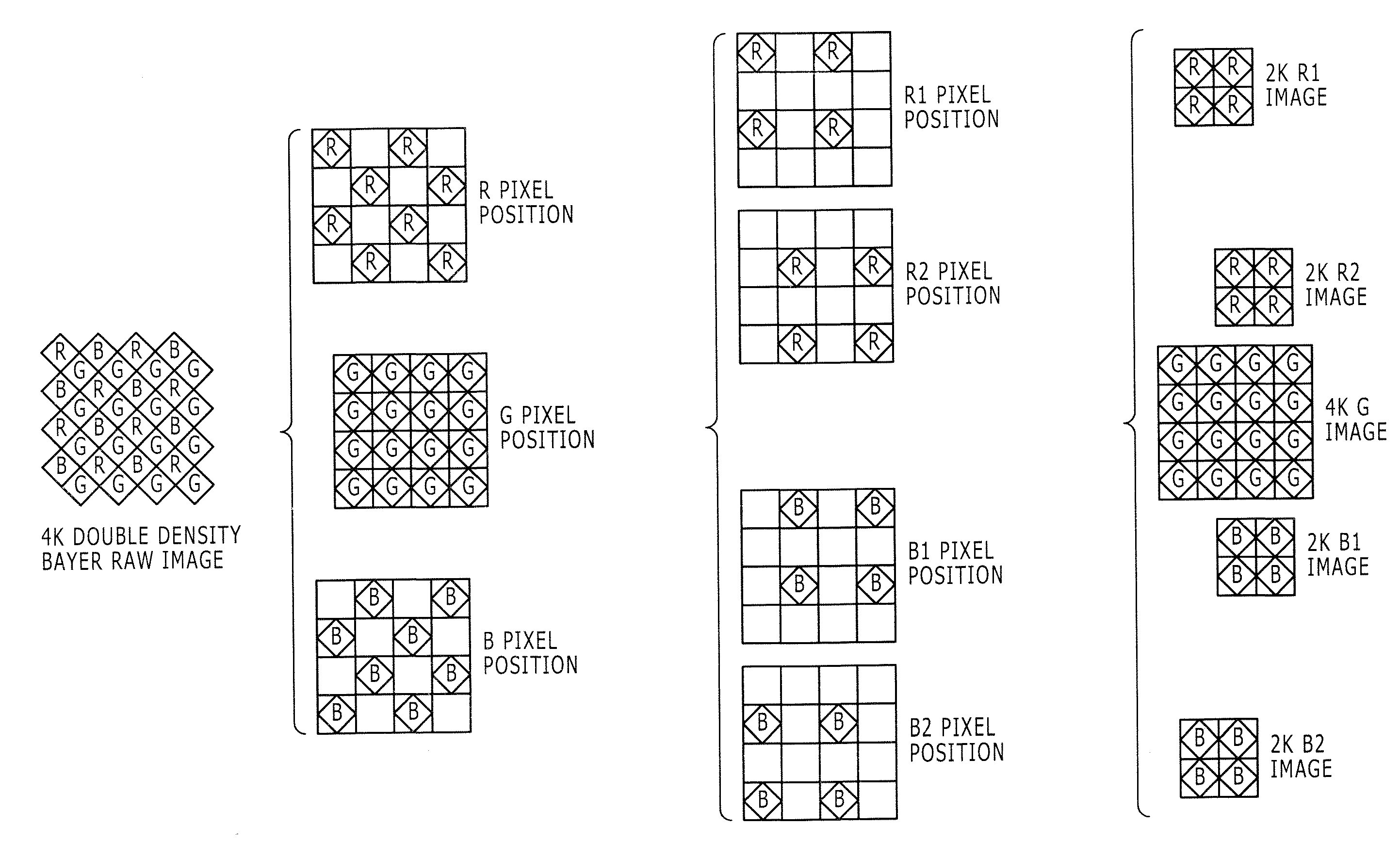
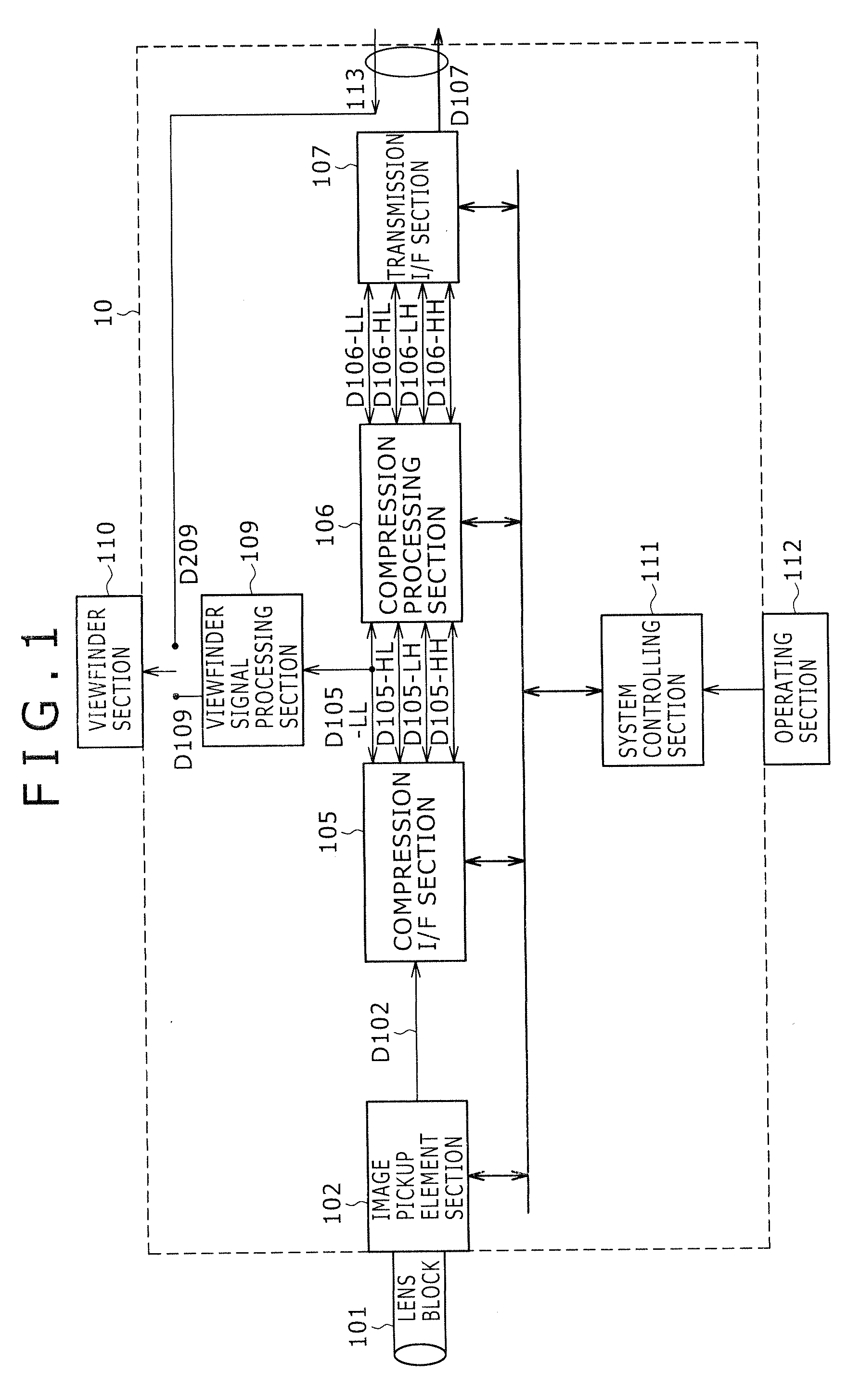
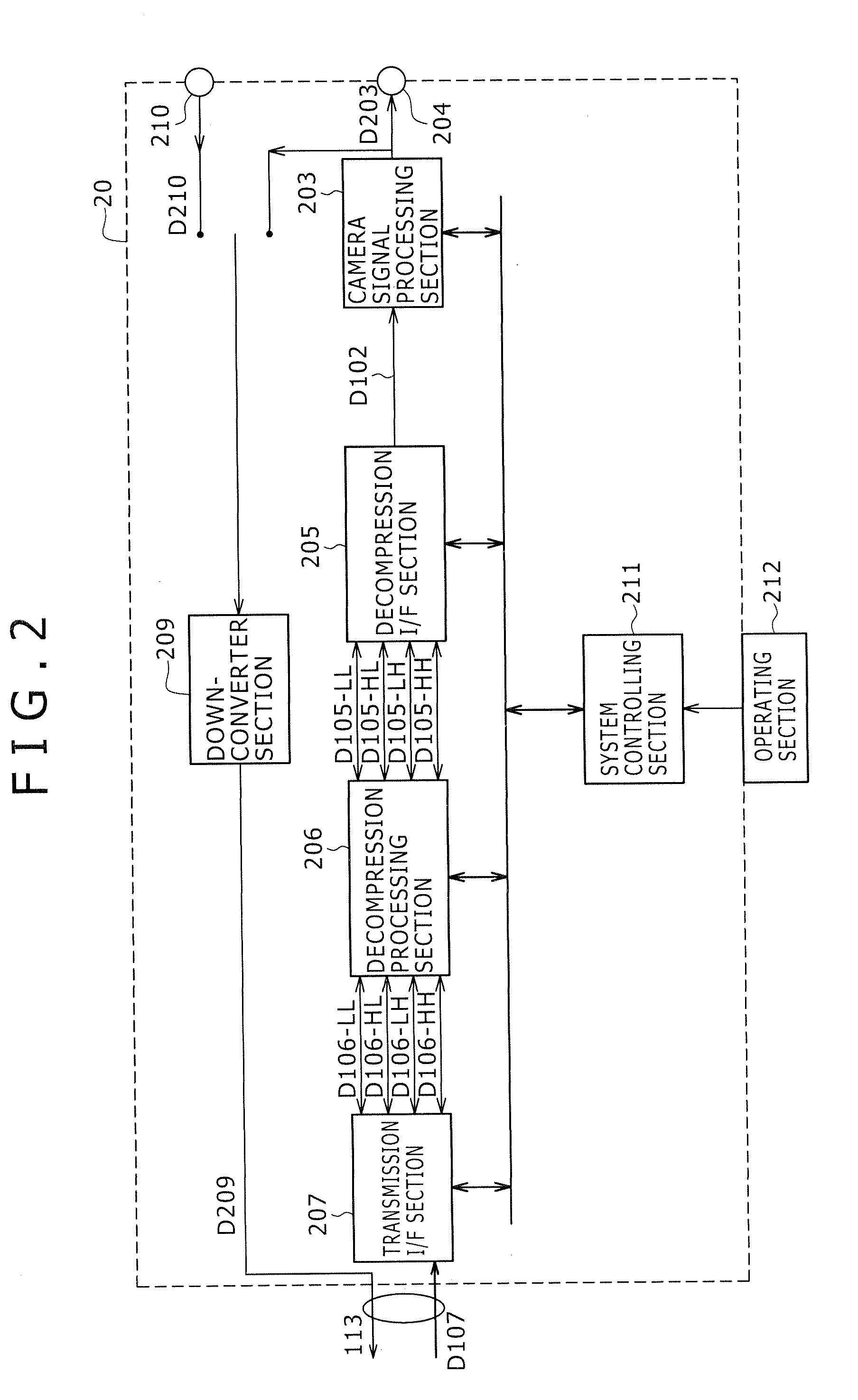
[0056]In the embodiment below, description will be made of an example applied to a camera system including: a camera section 10 for efficiently compression-coding each of three R / G / B components in any of RAW data obtained from an image pickup element of a Bayer arrangement without RGB full pixels, an image pickup element of a double density Bayer arrangement without RGB full pixels, and an image pickup system using three image pickup elements having pixels arranged in an oblique direction without RGB full pixels, resolving the RAW data into subband images, and outputting the subband images; and a CCU section 20 for decompressing the subband images received from the camera section 10 via a transmitting composite camera cable 113. Three co...

second embodiment

2. Second Embodiment

Example of Compression-Coding Image Using Haar Transform and Decoding Subband Images Using Inverse Haar Transform

[0338]An example applied to a camera section 10 according to a second embodiment of the present invention will next be described with reference to FIGS. 26A to 28D.

[0339]As described above, the compression I / F section 105 in combination with a wavelet transform provides a method of most effective compression. However, not only the wavelet transform but also a Haar transform that reduces a hardware load can realize the method.

[0340]At this time, the compression I / F section 105 subjects every two pixels adjacent to each other in an oblique direction in image data of a color in which pixel positions are alternately shifted from each other to a Haar transform with two upper and lower lines adjacent to each other as a unit. On the other hand, the decompression I / F section 205 decompresses subband images into the image data of the color whose pixel positions...


PUM


Abstract

Disclosed herein is a camera system including: a camera section including a subband dividing section configured to resolve image data of a color whose pixel positions are alternately shifted from each other into subband images, and a first transmission interface section configured to convert the subband images into a predetermined image signal, and output the image signal via a transmission line; and a camera control section including a second transmission interface section configured to convert the image signal input via the transmission line into the subband images, and an image decompressing section configured to decompress the subband images into the image data and synthesize the subband images into the image data output from the image pickup element.

Description

BACKGROUND OF THE INVENTION[0001]1. Field of the Invention[0002]The present invention relates to a camera system and an image processing method suitably applied to a case of efficiently compression-coding RAW data obtained from image pickup elements of various kinds of arrangement systems and decompressing the compression-coded RAW data, for example.[0003]2. Description of the Related Art[0004]An image pickup device using an image pickup element of a Bayer arrangement is generally known in the past. Such an image pickup element captures image light of a subject via a color filter, and outputs an image signal according to the intensity of the image light. Then, a subsequent processing section subjects the image signal to predetermined processing, whereby the image pickup device can display an image on a viewfinder or an external display device.[0005]In general, a camera system used for live broadcasts and the like includes a camera section used as an image pickup device and having an...

Claims


Application Information

Patent Timeline
Patent Type & Authority Applications(United States)
IPC IPC(8): H04N9/097H03M7/30H04N5/225H04N1/41H04N9/07H04N19/12H04N19/122H04N19/134H04N19/136H04N19/146H04N19/186H04N19/34H04N19/42H04N19/436H04N19/60H04N19/63H04N19/635H04N19/80H04N19/90H04N19/91
CPCH04N5/23203H04N9/045H04N19/436H04N19/124H04N19/146H04N19/63H04N23/66H04N23/843H04N25/134
Inventor SUGIYAMA, AKIRA
Owner SONY CORP
Why Eureka
Try Eureka