Linear solid-state lighting with shock protection switches

a solid-state lighting and switch technology, applied in the direction of semiconductor devices for light sources, lighting and heating apparatus, coupling device connections, etc., can solve the problems of led-based linear lighting systems that can only operate for 25,000 hours, the most detrimental to leds and led drivers, and the operating life of led-based lamps. , to achieve the effect of improving yield, reducing operating costs and reducing operating costs

Active Publication Date: 2011-06-23
ALEDDRA INC
View PDF5 Cites 124 Cited by
  • Summary
  • Abstract
  • Description
  • Claims
  • Application Information

AI Technical Summary

Benefits of technology

[0014]The present invention uses shock protection switches at both ends of the LLT lamp, at least one at each end, to fully protect the person from possible electric shock during re-lamping.
[0015]A linear light-emitting diode (LED)-based solid-state device comprising a heat sink, an LED driver, an LED printed circuit board (PCB) with a plurality of LEDs, a lens, and at least two shock protection switches, is used to replace a fluorescent tube in an existing fixture. With these shock-protection switches—at least one each at the two ends of the device, the LLT lamp prevents electric shock from happening during re-lamping. The two shock-protection switches with actuation mechanisms are engaged separately to connect the line and neutral of an external AC main to two inputs of the LED driver used to power LEDs in the LLT lamp. In such a scheme, no line voltage will possibly appear at the exposed bi-pin during re-lamping and thus any leakage current will be eliminated.
[0016]Modular design can increase manufacturing efficiency and improve yields. In this aspect, the present invention has a housing, which is preferably metallic in material and forms a hollow space lengthways under a platform. In the hollow space, the LED driver is inserted. On top of the platform, the LED PCB with a plurality of surface mount or DIP LEDs and a lens along the length are mounted. With two protection switches connected to the bi-pins through a lamp base assembly on both ends of the housing and the two inputs of the LED driver, the device can safely replace a fluorescent tube in an existing fixture. With a proper AC main connected, the device can emit warm white, natural white, day white, or cool white light corresponding to correlated color temperatures of 2,700˜3,200 K, 4,000˜4,500 K, 5,500˜6,000 K, 7,000˜7,500 K, depending on the LEDs used. Various combinations of various white, red, green, and blue LEDs are possible for implementing these correlated color temperatures.
[0017]In the present invention, thermal management not only for LEDs but also for LED driver and mechanical security of LED PCB, lamp bases, and the driver enclosure are implemented in such a way that the LLT lighting system is robust enough to maintain longevity.

Problems solved by technology

However, several factors may affect the operating life of an LED-based lamp.
High operating temperature is most detrimental to both LEDs and the LED driver that powers the LEDs.
In spite of longevity of LEDs, the LED-based linear lighting system can operate only around 25,000 hours.
This kind of LLT lamps always fails a safety test, which measures through lamp leakage current.
Because the line and the neutral of the AC main apply to both opposite ends of the tube when connected, the measurement of current leakage from one end to the other consistently results in a substantial current flow, which may present risk of shock during re-lamping.
Appliances such as toasters and other appliances with exposed heating filaments present this kind of hazard.
As mentioned, without protection, shock hazard will occur for an LLT lamp, which is at least 2 feet long; it is very difficult for a person to insert the two opposite bi-pins at the two ends of the LLT lamp into the two opposite sockets at two sides of the fixture at the same time.
In this case, however, the retrofit of the existing fixture to enable LLT lamp becomes complicated and needs much longer time to complete, even for electrical professionals.
The rewiring and installation costs will be too high for LLT lamp providers to replace conventional fluorescent tubes economically.
Another drawback for this rough manufacturing process is poor heat dispersion, which may cause overheating over a certain period under high ambient-temperature operation and shorten the LED driver's life and the lamp's life as a whole due to poor air convection and heat accumulation inside the LLT lamp 100.
The drawback for this is that no sufficient number of LEDs is on the LED PCB, thus affecting lumen output and efficacy of the lamp.
By using hard wires, the connections may not be reliable enough.
Furthermore, the LED PCBs in some conventional LLT lamps are glued on the platform using adhesives, which may present another reliability issue because the PCB may peel off from the platform under adverse operating environments such as high temperature and high humidity.
At this time, if the person who replaces the LLT lamp 100 touches the exposed bi-pin 190, which is energized, he or she will get electric shock because the current flows to earth through his or her body—a shock hazard.
Almost all LLT lamps currently available on the market are without any protection for such electric shock.
However, the one-switch approach cannot eliminate the possibility of shock risk.
As long as shock risk exists, the consumer product safety remains the most important issue.

Method used


Image

  • Linear solid-state lighting with shock protection switches
  • Linear solid-state lighting with shock protection switches
  • Linear solid-state lighting with shock protection switches

Examples


Embodiment Construction

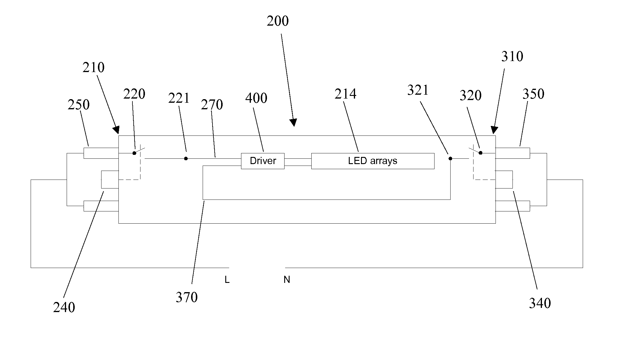
[0031]To protect consumers from possible electric shock during re-lamping, the present invention provides two special lamp bases, one for each end of the LLT lamp. Each lamp base contains a standard bi-pin and at least one shock protection switch, both mounted on a lamp base PCB, rather than on an end cover. This structure is different from that of the conventional LLT lamp, which uses two end caps in which the bi-pins are directly mounted.

[0032]FIG. 3 is an illustration of an LLT lamp according to the present invention. The LLT lamp 200 has a housing 201, two lamp bases 260 and 360, one at each end of the housing 201, two shock protection switches 210 and 310 in the two lamp bases 260 and 360, and an LED driver 400. The housing 201, preferably metallic in material, serves also as a heat sink with a toothed profile to increase the heat dispersion (see FIG. 9). Other types of projections can be formed on the outer surface of the housing for improved heat dispersion. On the top of the...


PUM


Abstract

A linear light-emitting diode (LED)-based solid-state device comprising at least two shock protection switches, at least one each at the two ends of the device, fully protects a person from possible electric shock during re-lamping with LED lamps.

Description

BACKGROUND OF THE INVENTION[0001]1. Field of the Invention[0002]This invention relates to linear light-emitting diode (LED) lamps and more particularly to a linear LED lamp with two shock protection switches, one at each of two ends of the lamp.[0003]2. Description of the Related Art[0004]Solid-state lighting from semiconductor light-emitting diodes (LEDs) has received much attention in general lighting applications today. Because of its potential for more energy savings, better environmental protection (no hazardous materials used), higher efficiency, smaller size, and much longer lifetime than conventional incandescent bulbs and fluorescent tubes, the LED-based solid-state lighting will be a mainstream for general lighting in the near future. Meanwhile, as LED technologies develop with the drive for energy efficiency and clean technologies worldwide, more families and organizations will adopt LED lighting for their illumination applications. In this trend, the potential safety con...

Claims


Application Information

Patent Timeline
Patent Type & Authority Applications(United States)
IPC IPC(8): F21S4/00H02H11/00
CPCF21V25/04F21Y2101/02H01R13/665F21K9/175H01R33/945H01R33/96F21Y2103/003H01R13/7036F21Y2103/10F21Y2115/10F21K9/272H05B47/26
Inventor HSIA, CHUNGHOSHEN, PAI-SHENGLIN, CHING-FENG
Owner ALEDDRA INC
Why Eureka
Try Eureka