Fixing device and image forming apparatus

a technology of fixing rollers and fixing rollers, which is applied in the direction of electrographic process equipment, instruments, optics, etc., can solve the problems of uneven gloss or hot offset, high rotation speed of fixing rollers, and pronounced temperature differences, so as to restrict the fluctuations of temperature ripples and control the effect of stably

Inactive Publication Date: 2011-06-23
RICOH KK
View PDF53 Cites 93 Cited by
  • Summary
  • Abstract
  • Description
  • Claims
  • Application Information

AI Technical Summary

Benefits of technology

[0009]Accordingly, the present invention provides a novel fixing device using the electromagnetic induction method and is capable of restricting fluctuations in the temperature ripples on the fixing roller and stably controlling the tem

Problems solved by technology

However, when the fixing roller is heated and rotated in a state where there is no sheet to be passed in a predetermined standby mode, the temperature difference becomes pronounced.
Starting the sheet passing operation in this state might result in uneven glossiness or hot offset in the resulting formed image.
However, in high-productivity image forming apparatuses, the rotatio

Method used


Image

  • Fixing device and image forming apparatus
  • Fixing device and image forming apparatus
  • Fixing device and image forming apparatus

Examples


Embodiment Construction

[0022]A fixing device and an image forming apparatus according to one embodiment of the present invention will now be described.

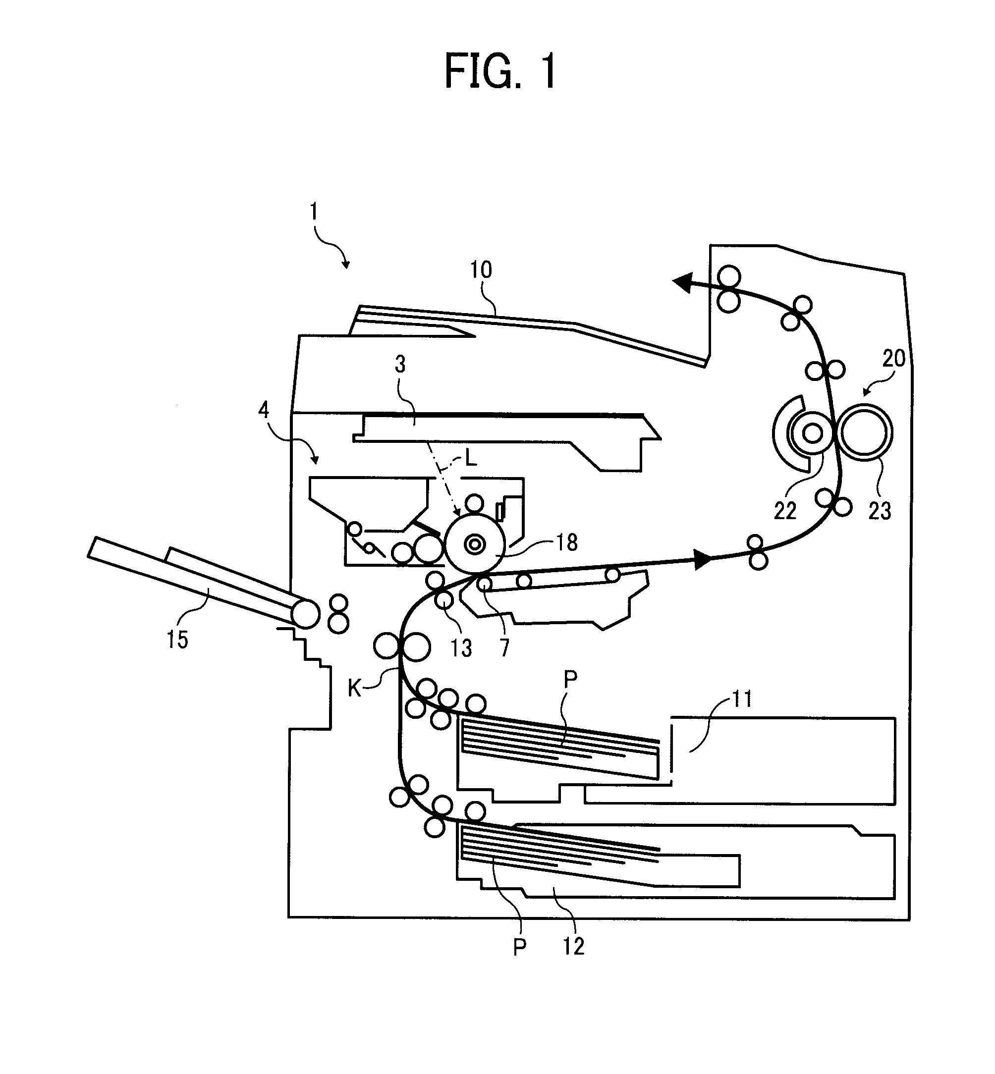
[0023]FIG. 1 shows a structure and operation of the image forming apparatus. The image forming apparatus herein is a laser printer, and includes an apparatus body 1, an exposure section 3, a process cartridge 4, a transfer section 7, a sheet discharge tray 10, sheet feed sections 11 and 12, a manual sheet feeder 15, and a fixing device 20. Based on image information, the exposure section 3 radiates exposure light L onto a photoreceptor drum 18; the process cartridge 4 serves as an image forming section detachably provided to the apparatus body 1; the transfer section 7 transfers a toner image formed on the photoreceptor drum 18 to a recording medium P; the sheet discharge tray 10 serves as a tray on which recording media carrying output image thereon are stacked; the sheet feed sections 11 and 12 serve to contain recording media P such as transfer sheets an...


PUM


Abstract

The fixing device using an electromagnetic induction heating (IH) method includes a fixing sleeve having a heating layer, a pressure roller to form a nip while contacting the fixing roller and rotate to drive the fixing sleeve, a temperature detector to detect a temperature on a circumference of the fixing sleeve, and an excitation coil provided near the fixing sleeve and configured to perform induction heating of the heating layer of the fixing sleeve based on the detection result from the temperature detector. The fixing device is configured to change a rotation speed of the fixing sleeve in a standby time during which the fixing sleeve, while rotating, is controlled to be heated so as to maintain a target temperature when a periodic temperature difference occurs on a circumference of the fixing rotary member and having a fluctuation amplitude larger than a predetermined value compared to the target temperature.

Description

CROSS-REFERENCE TO RELATED APPLICATIONS[0001]The present application claims priority from Japanese patent application number 2009-290483, filed on Dec. 22, 2009, the entire contents of which are hereby incorporated by reference herein.BACKGROUND OF THE INVENTION[0002]1. Field of the Invention[0003]The present invention relates to a fixing device using electromagnetic induction heating method and an electrophotographic or electrostatic image forming apparatus such as a fax, a printer, a copier and a multi-function apparatus combining the above functions equipped with the fixing device.[0004]2. Description of the Related Art[0005]A fixing device using an electromagnetic induction heating method (IH method) is configured such that electromagnetic fluxes are generated by causing a high frequency current to flow to an excitation coil or an IH coil, whereby a heat-generated member is induction-heated. According to this structure, the heating member is directly heated, which compares favor...

Claims


Application Information

Patent Timeline
IPC IPC(8): G03G15/20
CPCG03G15/2039G03G2215/2048
Inventor HASE, TAKAMASAEHARA, MASANAOISHII, KENJIOGAWA, TADASHIUENO, SATOSHISEO, HIROSHIIMADA, TAKAHIROYUASA, SHUUTAROH
Owner RICOH KK
Why Eureka
Try Eureka