Image forming apparatus

a technology of forming apparatus and forming tube, which is applied in the direction of electrographic process apparatus, thin material handling, instruments, etc., can solve the problems of difficult constant maintenance of a inability to continuously maintain a sheet conveying operation, and inability to generate a continuous loop amount of a sheet, so as to reduce the generation ratio of paper jam and paper wrinkle, the effect of reducing the generation of image deviation and rubbing

Active Publication Date: 2011-06-23
CANON KK
View PDF11 Cites 6 Cited by
  • Summary
  • Abstract
  • Description
  • Claims
  • Application Information

AI Technical Summary

Benefits of technology

[0010]According to the present invention, the contact portion is moved to the retracted position before the sheet tip end reaches the contact portion, and then, it is possible that a tip end of a sheet which enters the sheet conveying path fro...

Problems solved by technology

However, it is difficult to constantly maintain a conveying velocity of a sheet due to factors such as variation in machining precision of parts constituting the apparatus and thermal expansion, and as a result, it is difficult to constantly maintain a loop amount of a sheet.
To detect the loop amount described in Japanese Patent Application Laid-open No. 7-234604, if a mechanical sensor is disposed between the transfer apparatus and the fixing apparatus and the sensor is bro...

Method used


Image

  • Image forming apparatus
  • Image forming apparatus
  • Image forming apparatus

Examples


first embodiment

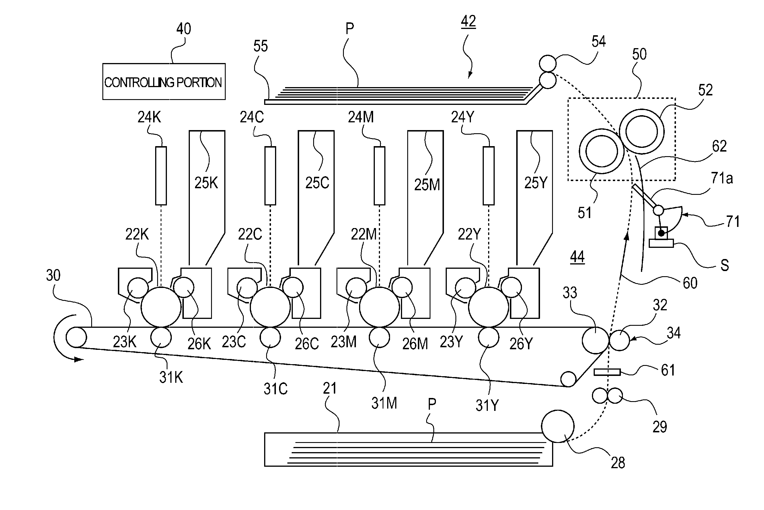
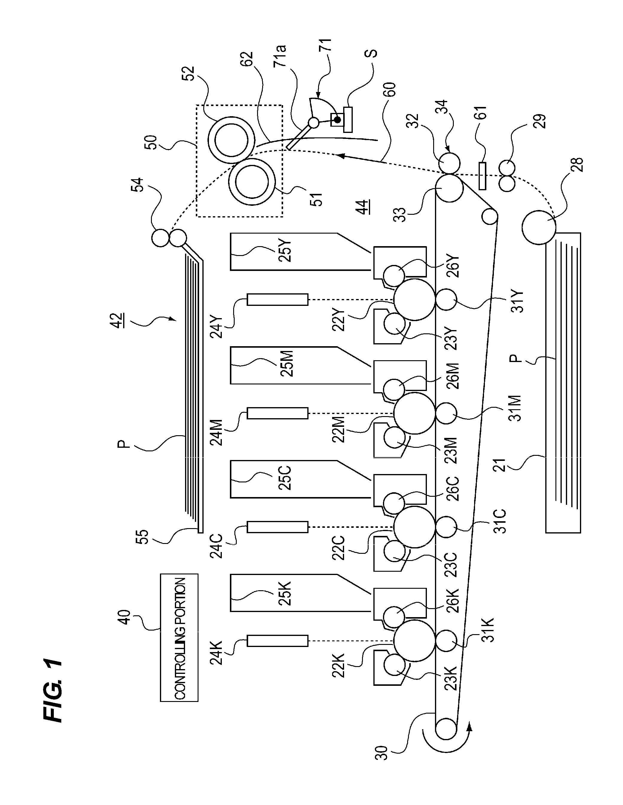
[0020]A first embodiment of the present invention will be described with reference to FIGS. 1 to 6. FIG. 1 illustrates one example of a color image forming apparatus of an electrophotographic system. First, an operation of the color image forming apparatus 42 of the electrophotographic system will be described using FIG. 1.

[0021]As illustrated in FIG. 1, the color image forming apparatus 42 includes a sheet feeding portion 21, photosensitive drums 22Y, 22M, 22C, and 22K, chargers 23Y, 23M, 23C, and 23K, toner cartridges 25Y, 25M, 25C, and 25K which are arranged in every station in a development color-coded manner. The color image forming apparatus 42 also includes development devices 26Y, 26M, 26C, and 26K, an intermediate transfer belt 30, primary transfer rollers 31Y, 31M, 31C, and 31K, a secondary transfer roller 32, a secondary transfer counter roller 33 and a fixing unit 50. The color image forming apparatus 42 forms an electrostatic latent image by exposure controlled by a con...

second embodiment

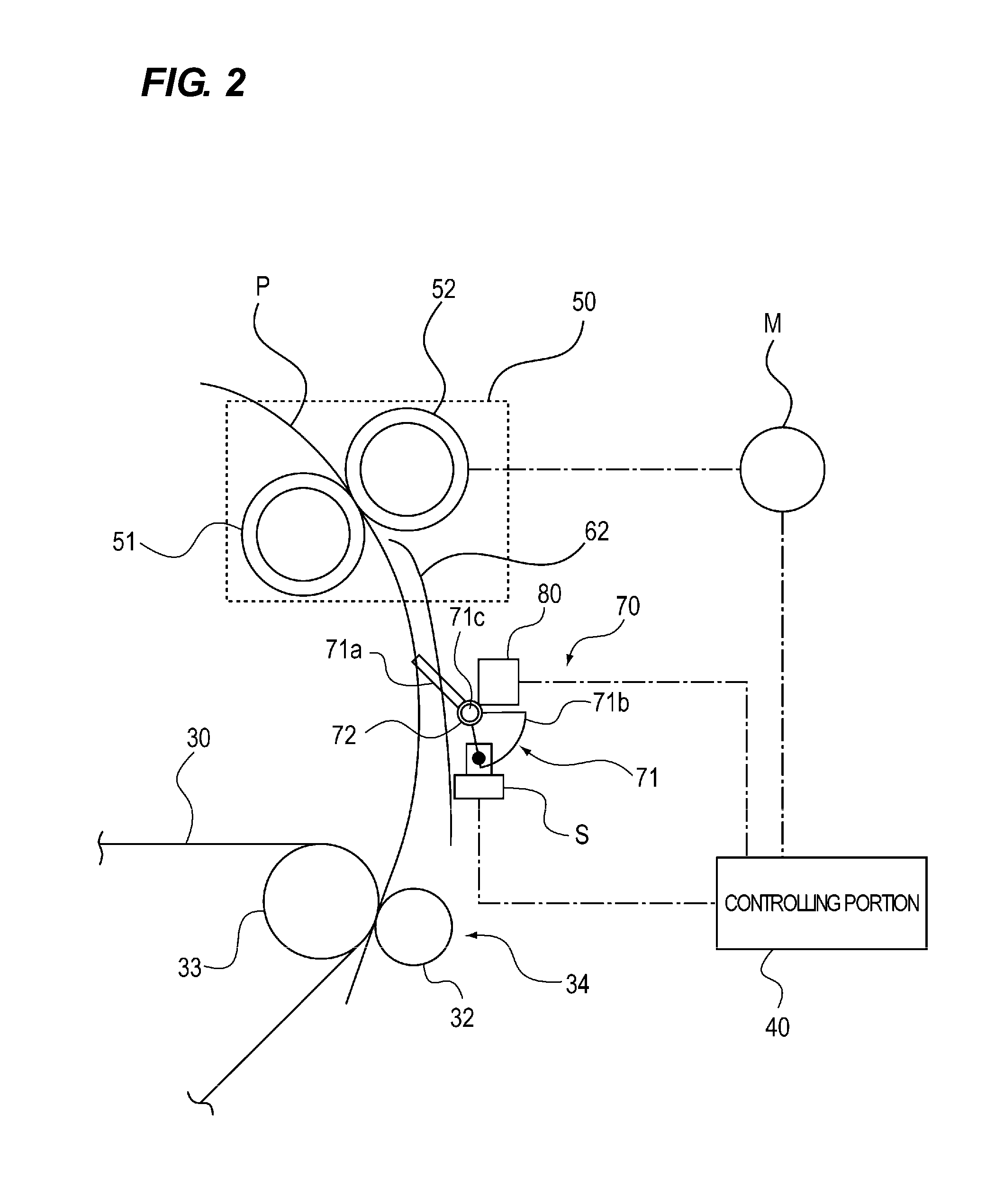
[0054]A second embodiment of the present invention will be described with reference to FIG. 8. A configuration and an image forming operation of an image forming apparatus of the second embodiment are the same as those of the color image forming apparatus 42 of the first embodiment. Members having the same functions as those of the color image forming apparatus 42 described in the first embodiment are designated with the same symbols, and description thereof will not be repeated. Portions of the image forming apparatus which are different from those of the color image forming apparatus 42 described in the first embodiment will be described mainly.

[0055]When sheets are continuously fed, i.e., when a precedent sheet P1 which has entered the sheet conveying path 60 passes through the contact portion 71a in the retracted position, if there is a subsequent sheet P2 which enters the sheet conveying path 60, the controlling portion 40 of this embodiment carries out the following control. T...


PUM


Abstract

The present invention provides an image forming apparatus including an upstream conveying portion, a downstream conveying portion, and a loop detector, wherein the image forming apparatus further includes a driving portion which moves the contact portion to a projecting position where the sheet conveying path is in contact with a conveyed sheet and to a retracted position where the sheet conveying path is not in contact with the conveyed sheet, and a controlling portion which controls the driving portion such that the contact portion is moved from the projecting position to the retracted position before a tip end of a sheet which enters the sheet conveying path from the upstream conveying portion reaches the contact portion.

Description

BACKGROUND OF THE INVENTION[0001]1. Field of the Invention[0002]The present invention relates to an image forming apparatus using an electrophotographic system such as a copying machine and a printer.[0003]2. Description of the Related Art[0004]According to a conventional image forming apparatus, when a sheet is nipped by a nip portion of a fixing apparatus and a transfer apparatus and conveyed in this state, if the sheet is pulled from the fixing apparatus, deviation or rubbing of an image is generated in some cases. To prevent the deviation and rubbing of an image, there is a known image forming apparatus having a configuration that a sheet is looped and conveyed in this state upstream of the fixing apparatus. According to this image forming apparatus, passing timing of a sheet is detected using a sensor which is disposed on an intermediate portion of a conveying path, a rotation velocity of a roller of the fixing apparatus is variably controlled according to the detected timing, ...

Claims


Application Information

Patent Timeline
IPC IPC(8): G03G15/00B65H7/00
CPCB65H5/062B65H7/02B65H2511/112B65H2553/612B65H2553/83G03G15/6573B65H2801/06B65H2220/01B65H2553/61
Inventor KASUGA, KUNIAKIFUKUZAWA, DAIZOSATO, NORIAKIYOSHIOKA, MAHITOKURATA, MUNEHITOIMAIZUMI, TOORU
Owner CANON KK
Why Eureka
Try Eureka