Bone graft applicator

a bone graft and applicator technology, applied in the field of bone graft applicators, can solve the problems of the delivery tip being collapsed, the prior art device designed to deliver bone graft material to the spine,

Inactive Publication Date: 2011-06-23
LARY RES & DEV
View PDF14 Cites 6 Cited by
  • Summary
  • Abstract
  • Description
  • Claims
  • Application Information

AI Technical Summary

Benefits of technology

[0017]The present invention provides a specially designed applicator, attached to a reservoir of bone graft material, such that the graft material can be moved into the delivery portion while the tip of the delivery portion is in place. The instantly disclosed device allows for the collapse of the delivery tip so that the tip can be placed between vertebras or alternatively within any bony structure or implant where the placement of bone graft material would be desirable, and then expanded to allow the bone graft material to be placed between the vertebras or the like while maintaining the geometry of the space into which the bone graft material is being placed.
[0019]It is a further objective of the instant invention to provide a bone graft applicator assembly which is suitable for placing bone graft material within an area via a minimally invasive technique.
[0020]It is yet another objective of the instant invention to provide an applicator assembly which maintains the geometry of the space during insertion of the bone graft material.

Problems solved by technology

Prior art devices designed to deliver bone graft material to the spine, such as those listed hereinafter, are fixed in nature and do not allow for the collapse of the delivery tip.

Method used


Image

  • Bone graft applicator
  • Bone graft applicator
  • Bone graft applicator

Examples


Embodiment Construction

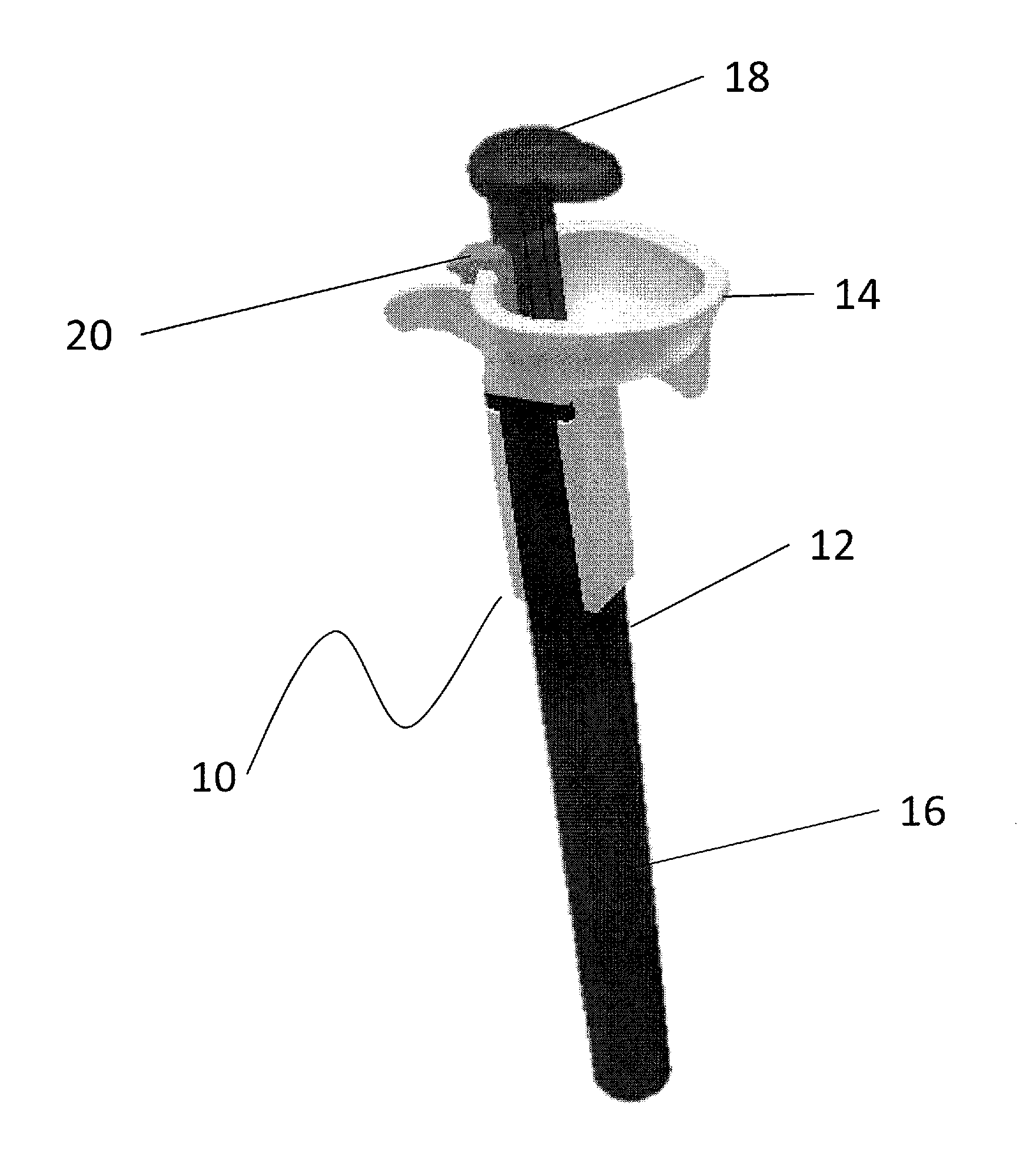
[0032]As will be explained in detail, with reference to the associated figures, a specially prepared applicator has been designed to provide for the traveling path of the bone graft material in relation to the vertebras to ensure a complete delivery to the desired location.

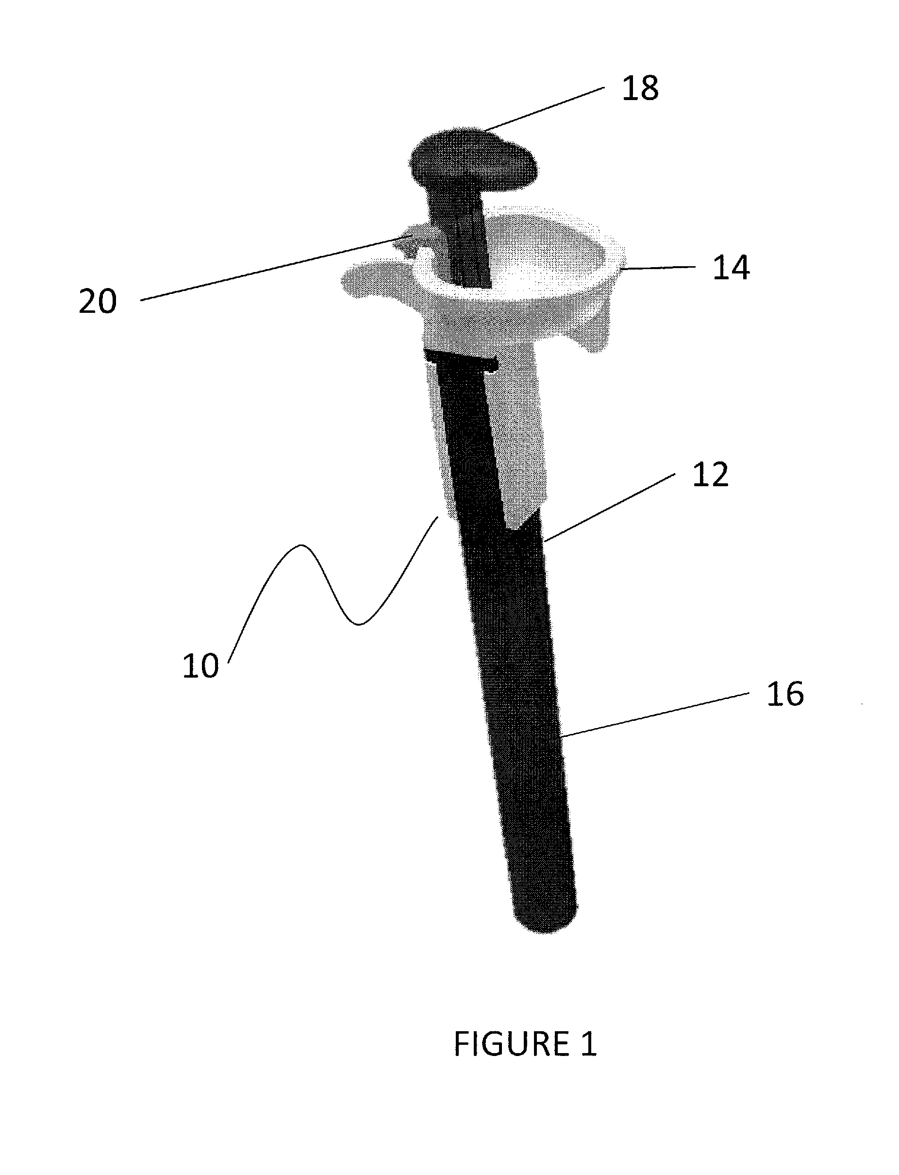
[0033]With reference to FIG. 1, a bone graft applicator assembly, generally referred to by the numeral 10, includes an applicator 12, a bone graft reservoir / funnel 14, an insert 16 and a plunger 18. The components of the bone graft applicator assembly 10, acting in concert, are designed to provide a predetermined path for the plunger 18 to travel. In addition, the components are designed in such a manner as to allow easy transfer of bone graft material (not shown) from the reservoir 14 to the applicator 12. Bone graft material may be taken from the hip or from another bone in the same patient (autograft) or from a bone bank (allograft). Bone graft extenders and bone morphogenetic proteins (hormones that cause bone...


PUM


Abstract

Disclosed herein is a bone graft applicator assembly including a specially designed applicator, attached to a reservoir of bone graft material, such that the graft material can be moved into the delivery portion while the tip of the delivery portion is in place. The instantly disclosed device allows for the collapse of the delivery tip so that the tip can be placed between vertebras or alternatively within any bony structure or implant where the placement of bone graft material would be desirable, and then expanded to allow the bone graft material to be placed between the vertebras or the like while maintaining the geometry of the space into which the bone graft material is being placed.

Description

REFERENCE TO RELATED APPLICATION[0001]This application claims benefit of the filing date of U.S. Provisional Patent Application No. 61 / 284,691, filed on Dec. 23, 2009, the contents of which is incorporated herein by reference in its entirety.FIELD OF THE INVENTION[0002]This invention relates generally to devices that are used deliver bone graft material. Moreover it pertains specifically to a device that is comprised of a bone graft reservoir, plunger and an applicator. Moreover it pertains specifically to collapsible devices that deliver bone graft material to the spinal region. It pertains to an apparatus that will place bone graft material between the vertebras.BACKGROUND OF THE INVENTION[0003]As opposed to traditional, open spine surgery which involves cutting or stripping the muscles from the spine, it has become common to perform spinal surgery using minimally invasive techniques, a treatment that involves small incisions and muscle dilation, allowing the surgeon to gently sep...

Claims


Application Information

Patent Timeline
Patent Type & Authority Applications(United States)
IPC IPC(8): A61M5/178
CPCA61F2/4601
Inventor CANTOR, JEFFREY B.LARY, BANNING G.LARY, TODD P.
Owner LARY RES & DEV
Why Eureka
Try Eureka