Radiotherapy apparatus

a technology of radiotherapy and apparatus, which is applied in the direction of radiation therapy, electrode and associated part arrangement, therapy, etc., can solve the problems of limiting the speed of the apparatus, the difficulty of accommodating the motion in a lateral direction with respect to the leaf, and the engineering consideration of the leaf, so as to minimise the penumbra and minimise the leakage between leaves.

Active Publication Date: 2012-03-20
ELEKTA AB
View PDF13 Cites 3 Cited by
  • Summary
  • Abstract
  • Description
  • Claims
  • Application Information

AI Technical Summary

Benefits of technology

[0011]It is also preferred that the support is constrained to tilt relative to the lateral motion as it moves along the path. Generally, the leaves within a multi-leaf collimator are not perfectly parallel but are each aimed so that they converge—the point of convergence can be on the source of radiation in order to minimise any penumbra caused by the leaves or (preferably) offset relative to the source so as to minimise leakage between leaves. Thus, it is preferred that the arcuate path is linear, with the tilt allowing the geometry of the leaves to be substantially maintained notwithstanding the lateral movement of the support.

Problems solved by technology

In particular, whilst such a link works well in theory, and will work well in practice for movements of tumours that are in the longitudinal direction relative to the leaves (i.e. in the direction of leaf motion) there will be difficulties in accommodating motion in a lateral direction with respect to the leaf, i.e. perpendicular to the direction of leaf motion.
Such speeds are limited by engineering considerations and, in particular, the practicalities of moving very thin very heavy leaves in confined spaces.

Method used


Image

  • Radiotherapy apparatus
  • Radiotherapy apparatus
  • Radiotherapy apparatus

Examples


Embodiment Construction

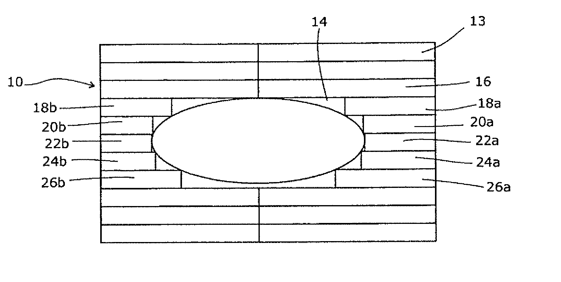
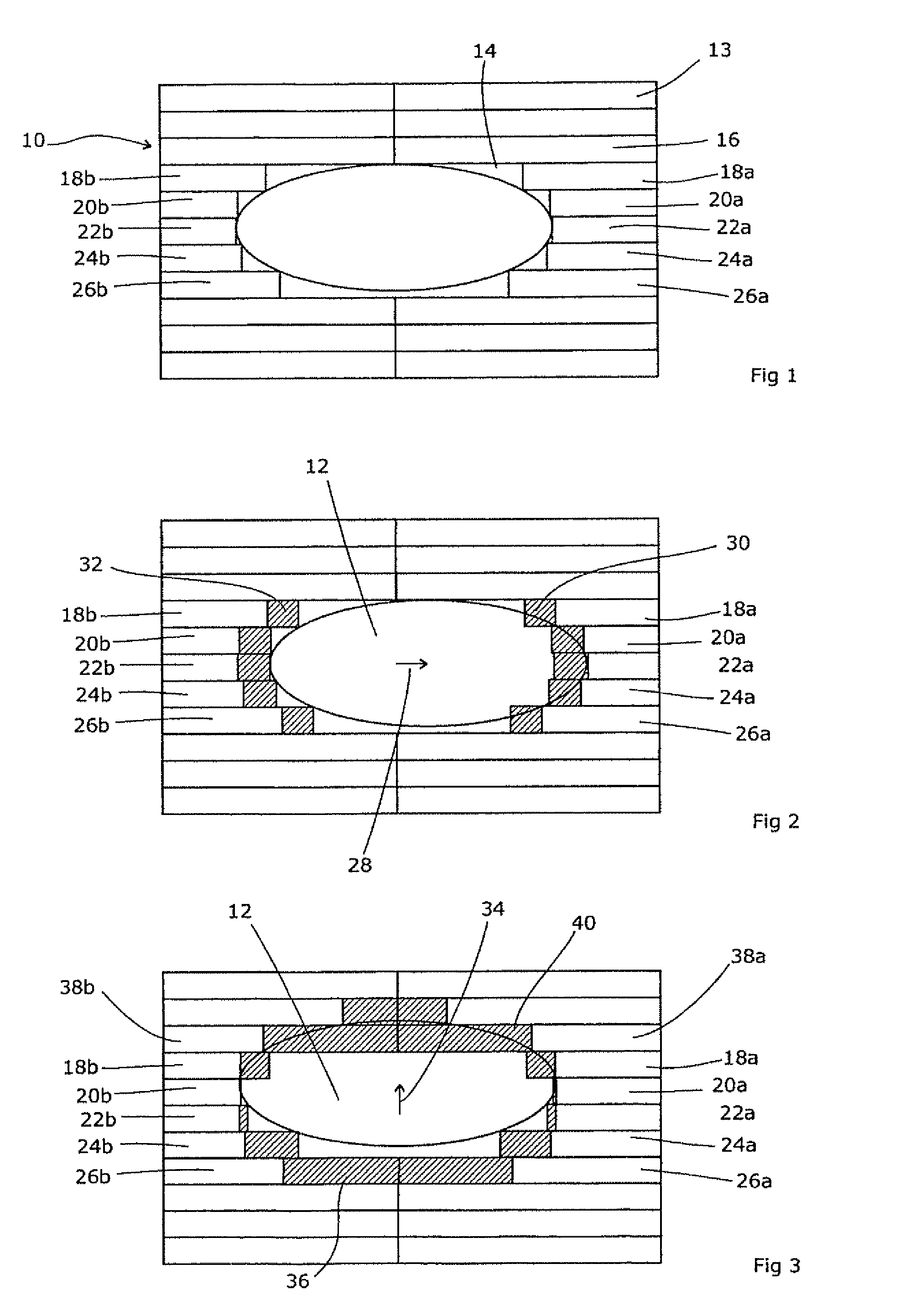
[0021]Referring to FIG. 1, a known form of multi-leaf collimator 10 is used to delimit a radiation beam intended to treat a tumour 12. Viewed along the axis of the radiation beam as in FIG. 1, the multi-leaf collimator 10 consists of a plurality of leaves 13 which are generally deep in the direction of the beam, elongate in a longitudinal direction transverse to the beam, and narrow in a lateral direction perpendicular to the beam. They are then arranged in an array alongside each other with their lateral faces closely adjacent and parallel. They are mounted in a support (not shown in FIG. 1) which allows individual leaves to be extended or retracted so as to define a shape 14 which generally matches the exterior of the tumour 12 as viewed along that axis. Some of the leaves such as leaf 16 are extended fully to the middle of the field, whereas adjacent leaves 18a, 20a, 22a, 24a and 26a are partially retracted so as to expose the tumour 12 to radiation. A corresponding situation exi...


PUM


Abstract

Realtime beam shape adjustment in response to (for example) online CT scanning of a patient during treatment is assisted by the radiotherapy apparatus comprising a source adapted to emit a beam of therapeutic radiation, a collimator for delimiting the radiation beam, the collimator comprising a plurality of leaves arranged alongside each other and be moveable longitudinally so that the tips of the leaves define a variable edge of the collimator, the leaves being mounted on a support that is moveable laterally with respect to the leaves. In this way, movements of the tumor that are perpendicular to the direction of leaf motion can be accommodated by simply moving the collimator bodily so as to accommodate this. It is preferred that the apparatus also includes a control means adapted to receive information as to the location of the target volume, and, on the basis of that information, control the longitudinal positions of the leaves and the lateral position of the support. It is also preferred that the support tilts as it moves laterally along a path. This can be achieved, by example, by bearings that are moveable on suitable guides, or by mounting the support on a plurality of pivot arms of unequal lengths. The lengths of such pivot arms can be adjusted as necessary.

Description

[0001]This Application is a Section 371 National Stage Application of International Application No. PCT / EP2007 / 009404, filed Oct. 30, 2007 and published as WO 2009 / 056151 A1 on May 7, 2009, the content of which is hereby incorporated by reference in its entirety.FIELD OF THE INVENTION[0002]The present invention relates to radiotherapy apparatus, and is especially concerned with the control of multi-leaf collimators therefor.BACKGROUND ART[0003]Radiotherapy apparatus involves the production of a beam of ionising radiation, usually x-rays or a beam of electrons or other sub-atomic particles. This is directed towards a cancerous region of the patient, and adversely affects the tumour cells causing an alleviation of the patient's symptoms. Generally, it is preferred to delimit the radiation beam so that the dose is maximised in the tumour cells and minimised in healthy cells of the patient, as this improves the efficiency of treatment and reduces the side effects suffered by a patient. ...

Claims


Application Information

Patent Timeline
Patent Type & Authority Patents(United States)
IPC IPC(8): G21K1/04A61N5/10
CPCA61N5/1042A61N5/1049A61N5/1067A61N2005/1061
Inventor BROWN, KEVINSTREAMER, RALPHBOURNE, DUNCAN
Owner ELEKTA AB
Why Eureka
Try Eureka