Pointer detection apparatus and pointer detection method

a detection apparatus and pointer technology, applied in the direction of speed measurement using gyroscopic effects, instruments, surveying and navigation, etc., can solve the problems of long process time and inapplicability of conventional pointer detection apparatus to practical us

Active Publication Date: 2011-06-23
WACOM CO LTD
View PDF50 Cites 73 Cited by
  • Summary
  • Abstract
  • Description
  • Claims
  • Application Information

AI Technical Summary

Benefits of technology

The pointer detection apparatus and method described in this patent can detect the presence and position of a pointer on a conductor pattern simultaneously at multiple cross points. This means that multiple pointers and their positions can be detected faster and more efficiently.

Problems solved by technology

The technical problem addressed in this patent text is to improve the detection of a pointer on a touch panel or the like using an electrostatic coupling system. The text describes various techniques for optimizing the configuration of a sensor section and associated elements of a pointer detection apparatus, including the use of resistive film systems and cross point electrostatic coupling systems. The cross point electrostatic coupling system uses a sensor section with a transparent substrate or film on which transmission and reception conductors are patterned to detect the position of a pointer. The position of the pointer is determined by detecting variations in current flowing through the pointer and its cross points on the sensor section. The patent text describes the operation of the cross point system and the level variation of the output signal from the differential amplifier. The technical problem addressed is to improve the accuracy and efficiency of pointer detection in a more efficient and effective way.

Method used


Image

  • Pointer detection apparatus and pointer detection method
  • Pointer detection apparatus and pointer detection method
  • Pointer detection apparatus and pointer detection method

Examples


first embodiment

1. examples of a basic configuration;

2. Second Embodiment: examples of a configuration which uses a PSK-modulated spread code;

3. Third Embodiment: examples of a configuration which uses an FSK-modulated spread code;

4. Fourth Embodiment: different supplying methods of a spread code;

5. Fifth Embodiment: selection methods of a reception conductor;

6. Sixth Embodiment: different examples of a configuration of a sensor section;

7. Seventh Embodiment: different examples of a configuration of an amplification circuit; and

8. Eighth Embodiment: detection of hovering.

1. First Embodiment

Examples of a Basic Configuration

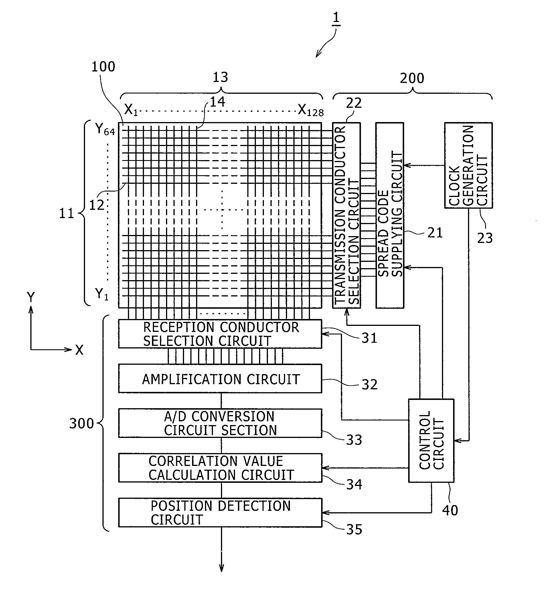
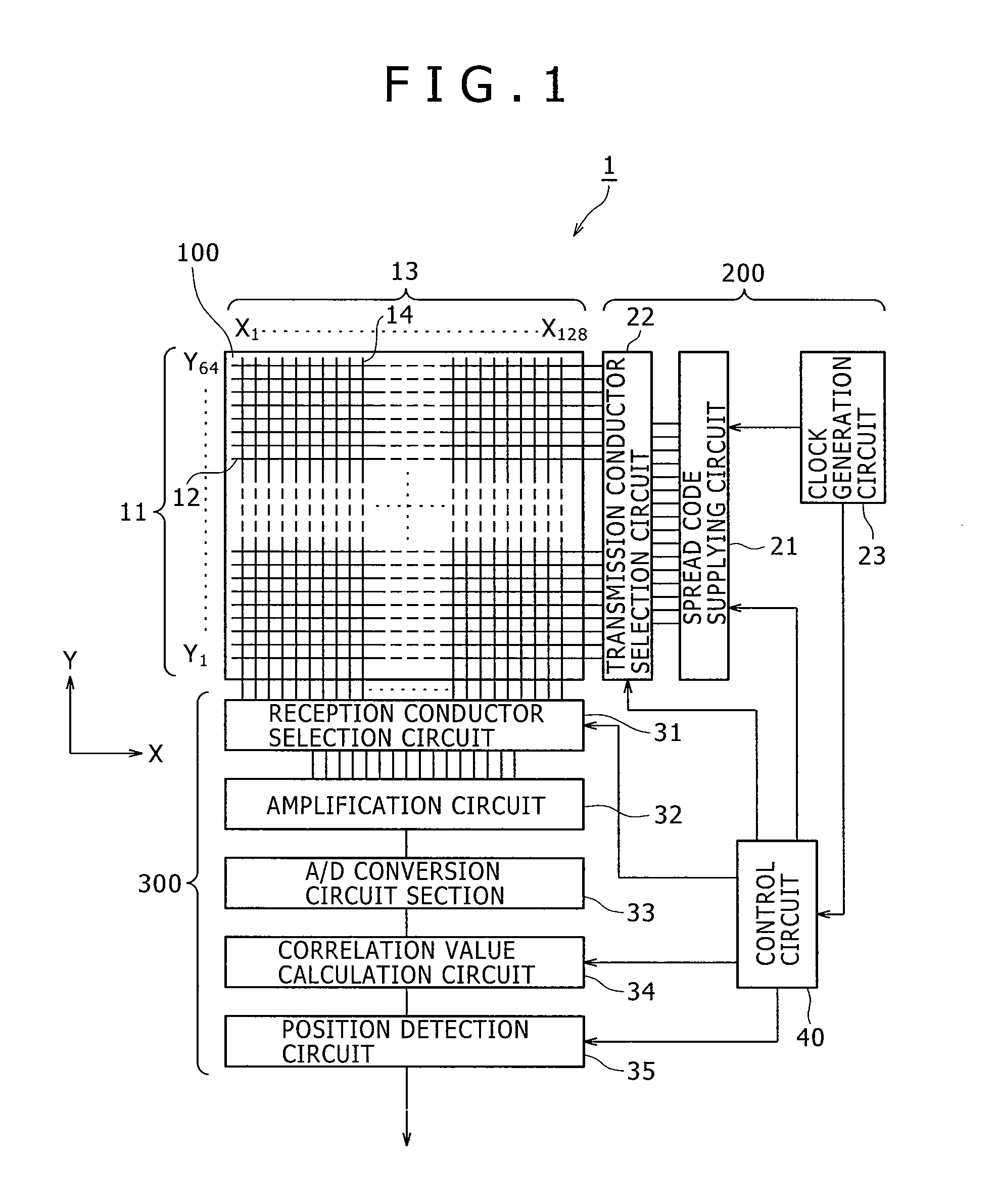
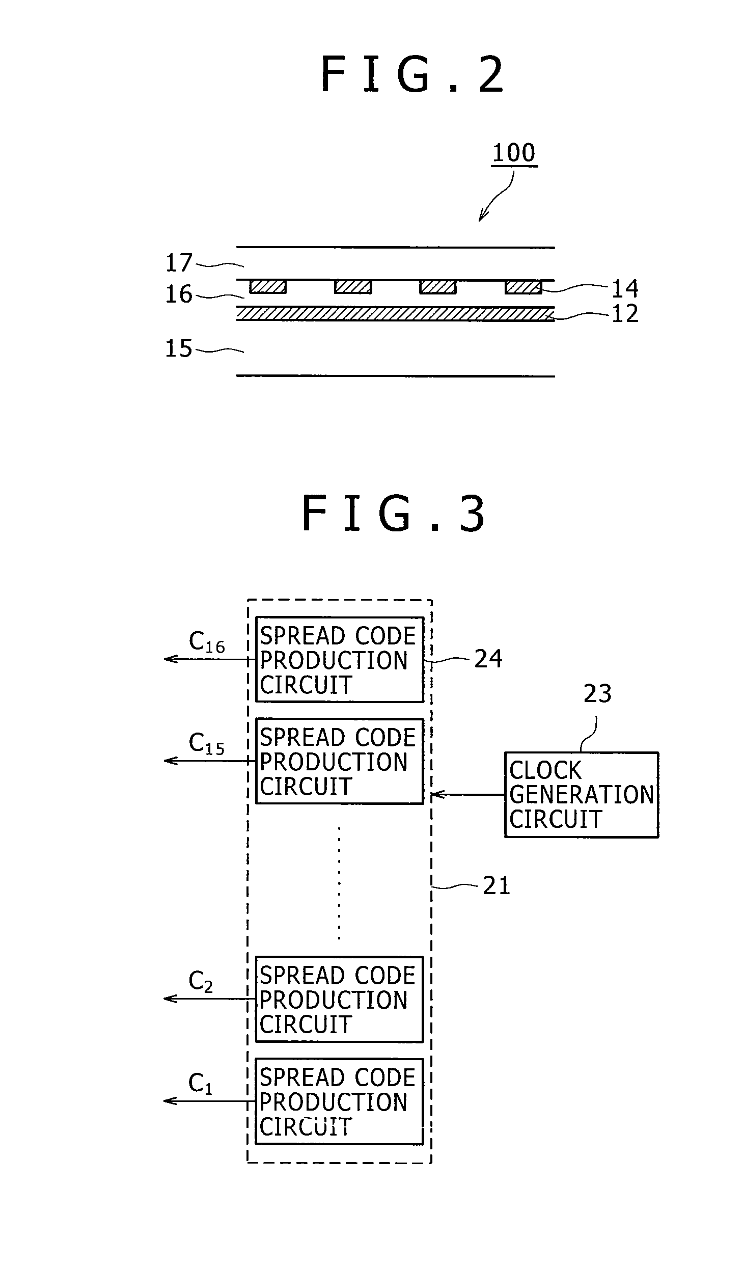
[0093]An example of a basic configuration of a pointer detection apparatus and a pointer detection method according to the present invention is described with reference to FIGS. 1 to 18. It is to be noted that, as a position detection method in the present invention, an electrostatic coupling method is used for detecting the position of a pointer based on the variation of an elec...

second embodiment

2. Second Embodiment

Examples of a Configuration which Uses a PSK-Modulated Spread Code

[0198]While, in the first embodiment described above, the spread codes Ck are supplied directly to the transmission conductor array 11, the present invention is not limited to this configuration. For example, the spread codes Ck may be supplied to the transmission conductor array 11 after predetermined modulation is applied thereto. The second embodiment is directed to an example of a configuration wherein the spread codes Ck to be supplied to the transmission conductor array 11 are PSK (Phase Shift Keying) modulated.

[PSK Modulation]

[0199]FIGS. 19A and 19B illustrate waveforms of spread codes before and after PSK modulation. In particular, FIG. 19A illustrates a waveform of a spread code before PSK modulation and FIG. 19B illustrates a waveform of the spread code after the PSK modulation.

[0200]In the present second embodiment, the spread codes Ck are PSK modulated with a signal having a clock perio...

third embodiment

3. Third Embodiment

Examples of a Configuration which Uses an FSK-Modulated Spread Code

[0213]The third embodiment is configured such that the spread codes Ck to be supplied to the transmission conductor array 11 are FSK (Frequency Shift Keying) modulated.

[FSK Modulation]

[0214]FIGS. 23A and 23B illustrate waveforms of spread codes before and after FSK modulation, respectively.

[0215]In the third embodiment described below, a signal of a clock frequency equal to, for example, twice or four times the clock frequency of the spread codes Ck before modulation (i.e., the chip rate) is used for FSK modulation. It is to be noted that the present invention is not limited to this configuration and the ratio between the clock frequency for modulation and the chip rate can be changed suitably according to each application or the like. In the FSK modulation in the present third embodiment, a signal of a High level state in the spread codes before modulation illustrated in FIG. 23A corresponds to a ...


PUM


Abstract

A pointer detection apparatus and a pointer detection method of the cross point electrostatic coupling type are disclosed, by which a pointer on a conductor pattern can be detected at a higher speed. The pointer detection apparatus includes a conductor pattern, a spread code supplying circuit, a reception conductor selection circuit, an amplification circuit, an analog to digital conversion circuit, and a correlation value calculation circuit. The spread code supplying circuit supplies a plurality of spread codes at the same time. The correlation value calculation circuit determines correlation values between signals output from the analog to digital conversion circuit and the correlation calculation codes respectively corresponding to the spread codes. A pointer is detected based on the determined correlation values.

Description


Claims


Application Information

Patent Timeline
Owner WACOM CO LTD
Why Eureka
Try Eureka