Object sensor

a technology of object angle and sensor, which is applied in the direction of mechanical measuring arrangement, using reradiation, instruments, etc., can solve the problems of sensor misalignment, motor vehicle misalignment, and impaired accuracy of object position determination

Active Publication Date: 2011-06-23
ROBERT BOSCH GMBH
View PDF2 Cites 24 Cited by
  • Summary
  • Abstract
  • Description
  • Claims
  • Application Information

AI Technical Summary

Benefits of technology

[0010]Based on the cross-misalignment angle, both the detection of an existing misalignment and compensating for it are able to be improved. The cross-misalignment angle, in particular, permits determining the presence of a misalignment, independently of compensation for it, in a rapid and reliable manner. To determine a relative misalignment, measurements may be used both on an immovable and on a movable object, such as a preceding motor vehicle. The compensation is able to take place directly based on the cross-misalignment angle, for instance, in the form of a compensation of the object angle by the cross-misalignment angle by an angle addition. The compensation may also be indirectly based on the determined cross-misalignment angle, for instance, by initiating a conventional compensation method or by changing parameters of a conventional compensation method in a targeted fashion. The postconnected system may be deactivated using the validity signal, until the misalignment compensation has taken place at a sufficient quality. At first, only a relative misalignment is determined, in this instance, that is, the rotation of a sensor with respect to the other one. During the further course of the technique presented, a rotation of both sensors in the same direction may also be compensated for.
[0011]The sensors may be at a distance with respect to each other, and in order to determine the directional angle, the directional angles recorded by the sensors may be transposed into a common reference system. It is generally desirable for geometrical reasons to maximize a base line between the sensors, transversely to the direction of motion of a reference system (of a motor vehicle), so that the sensors on a motor vehicle are frequently mounted front left and front right. In order to be able to compare to each other the directional angles determined by the sensors, a point of origin of a common reference system (coordinate system may be defined, for example, on the base line connecting the sensors on the center axis of the motor vehicle. The transposing takes place while knowing the position of the sensors with respect to the common reference system, and may be carried out efficiently, for instance, using matrix operations.
[0012]The validity signal may be determined using a histogram filter. The histogram filter classifies incoming cross-misalignment angles in the value range and manages the counter readings of the bins assigned to the value ranges. The validity signal may be determined with the aid of different observed magnitudes at the histogram filter. Filtering using a histogram filter does not require measurements at a distance in time, but the filtering speed is mainly a function of measuring frequency, so that the determination is able to be carried out quickly and reliably. The determination of the validity signal may include a comparison with a predetermined threshold value.
[0015]Based on the object angles of the same object at different positions with respect to the reference system of the sensors, one is able to determine a compensation angle. The object may be a roadway marking, for instance, or a street sign whose directional angles are determined at different distances from the motor vehicle. A compensation angle may be determined based on the change in the directional angles determined, which either has reference to a directional angle of one sensor or is based on the values of the object angle determined by both sensors. This procedure is able to supplement or support the detection and / or compensation of a misalignment of a sensor, based on the cross-misalignment angle.
[0020]The sensors may be at a distance from one another, and the device may include a transposing apparatus for transposing directional angles, recorded by the sensors, into a common reference system. This simplifies further processing of the transposed directional angles by other systems.

Problems solved by technology

A gradual misalignment with respect to the motor vehicle, that is progressive over a longer period of time, is improbable according to past experience.
However, the misalignment of a sensor may occur, for example, by a relatively slight influence of an external object on the motor vehicle or its attachment parts, perhaps by a light collision, which may take place during parking or leaving a parking space.
If a sensor is misaligned, the accuracy of the determination of the position of the object may be impaired, so that, under certain circumstances, a postconnected driver assistance system is not able to fulfill its task satisfactorily or at all.

Method used


Image

  • Object sensor
  • Object sensor
  • Object sensor

Examples


Embodiment Construction

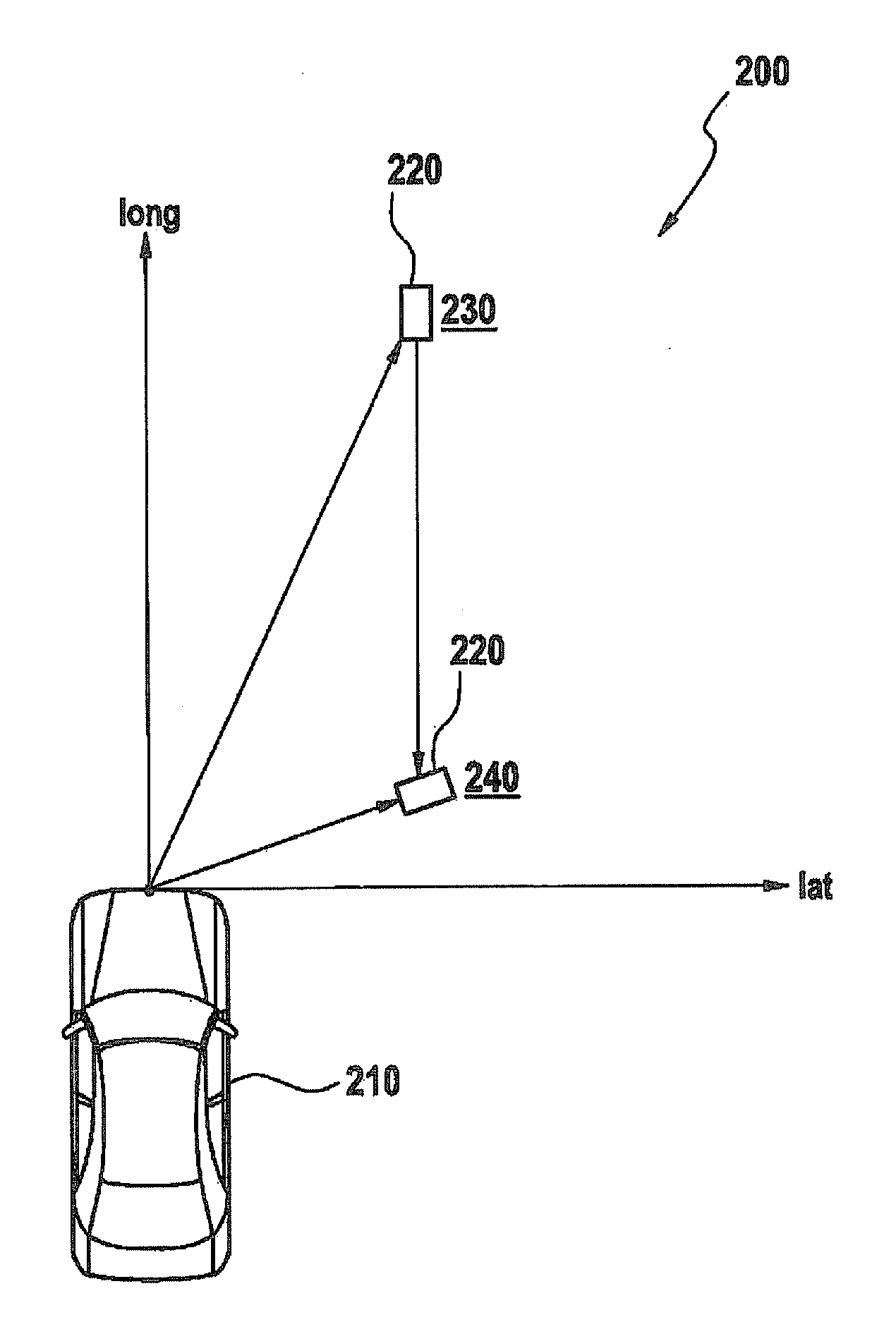
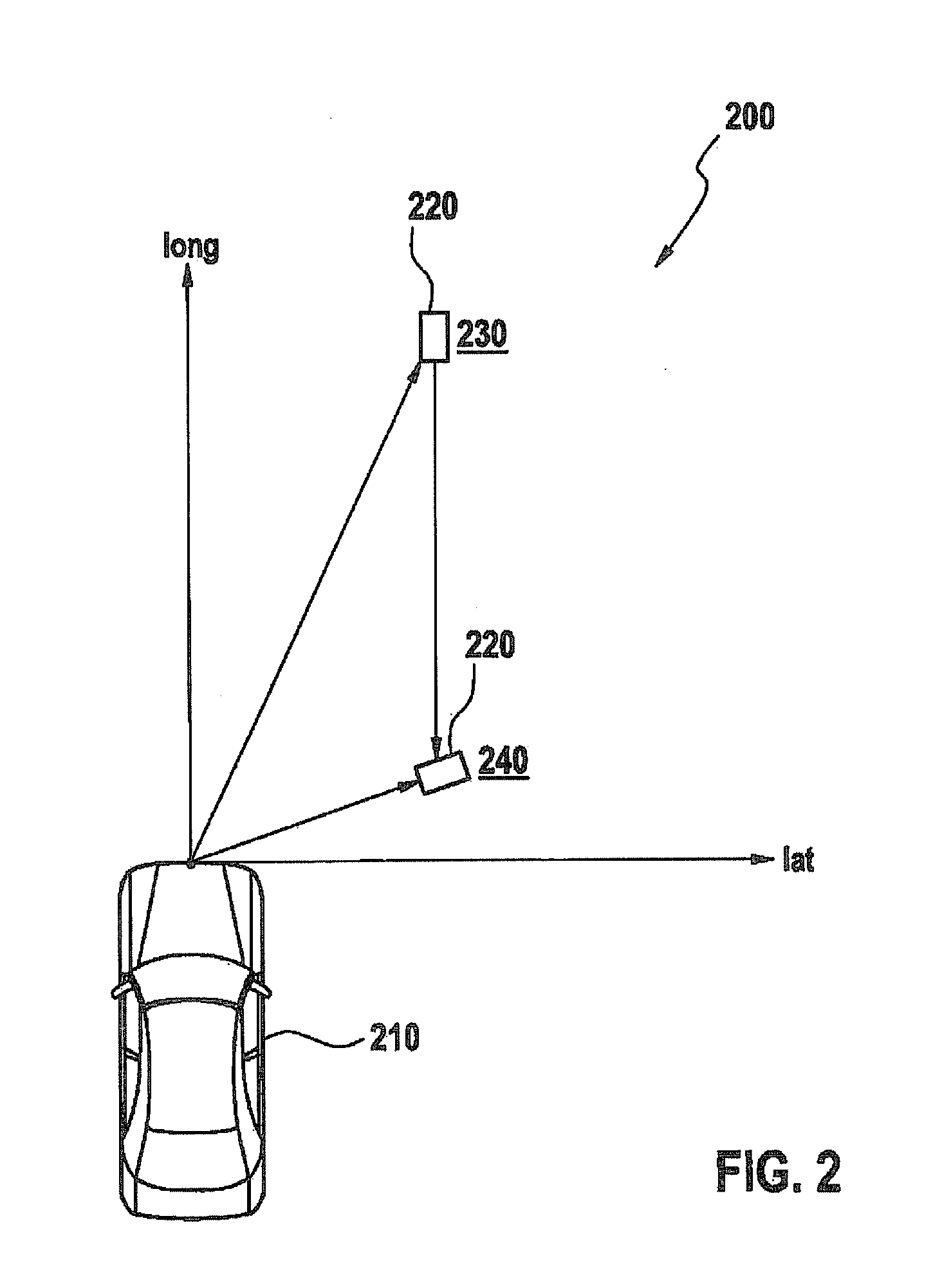
[0027]Designations for different angles include those below:

directional angle: an angle to the object determined by a sensor L, R.

object angle: the actual angle at which an object appears in a common coordinate system.

angle of misalignment: the angle by which one of sensors L, R is rotated with respect to the common coordinate system.

object hypothesis: the angle of the object determined by the overall system in the common coordinate system.

cross-misalignment angle: the difference of transposed directional angles.

system angle: the difference between the coordinate system formed from the directional angles of the sensors L, R and the coordinate system of the vehicle.

compensation angle: the determined approximation to a misalignment angle.

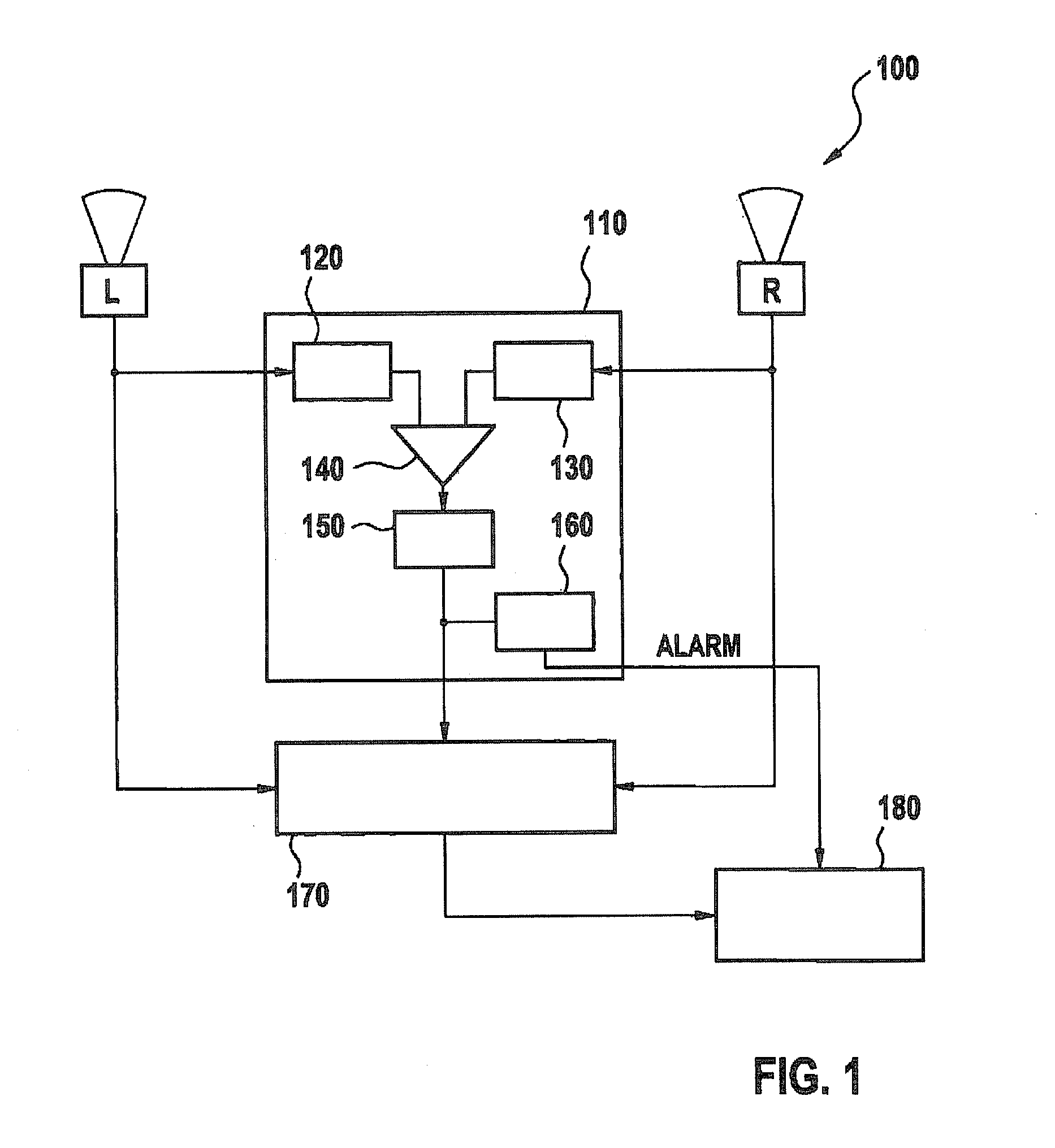
[0028]FIG. 1 shows a block diagram of a device 100 for determining an object angle having a postconnected driver assistance system 180. In each case, two sensors L and R determine a directional angle of an object (not shown), which is located in a com...


PUM


Abstract

A method for determining an object angle, especially for a driver assistance system in a motor vehicle, includes the steps of determining directional angles of the object with respect to two sensors, determining the object angle based on the directional angles, determining a cross-misalignment angle as the difference of the determined directional angles, determining a validity signal indicating the validity of the object angle based on the cross-misalignment angle and compensating for the influence of a relative misalignment of the sensors on the determined object angle based on the cross-misalignment angle.

Description

CROSS REFERENCE[0001]The present application claims the benefit under 35 U.S.C. §119 of German Patent Application No. 102009054835.1 filed on Dec. 17, 2009, which is expressly incorporated herein by reference in its entirety.FIELD OF THE INVENTION[0002]The present invention relates to a technique for recording an object angle. The present invention particularly relates to a method and a device for determining an object angle for a driver assistance system in a motor vehicle.BACKGROUND INFORMATION[0003]Increasingly, motor vehicles are being equipped with driver assistance systems, which support and relieve the load on the driver of the motor vehicle. Examples of such assistance systems include the ACC system (adaptive cruise control) for speed control or a PSS system (predictive safety system) for farsighted vehicle control, which may include, for example, a PBA system (predictive brake assist) for farsighted brake support, or a PEB system (predictive emergency braking) for farsighte...

Claims


Application Information

Patent Timeline
Patent Type & Authority Applications(United States)
IPC IPC(8): G01B5/25G06F15/00G01S13/931G01S15/931G01S17/931
CPCG01S13/931G01S2013/9375G01S17/936G01S2013/9364G01S2013/9367G01S7/4026G01S7/4972G01S13/86G01S7/52004G01S7/295G01S13/42G01S13/878G01S2007/4091G01S2007/403G01S15/931G01S2013/9323G01S2013/9324G01S2013/93271G01S17/931G01S7/403G01S7/4091
Inventor JORDAN, RUEDIGERREITER, IRIS NADINE
Owner ROBERT BOSCH GMBH
Why Eureka
Try Eureka