

Straddle-Type Vehicle
a technology of a stance and a steering wheel, which is applied in the direction of vehicles, cycle frames, cycle equipment, etc., can solve the problems of reducing the flexibility of the attitude of the driver mounting the motorcycle, during driving, etc., and achieve the effect of improving the flexibility of the driver's attitud
- Summary
- Abstract
- Description
- Claims
- Application Information
AI Technical Summary
Benefits of technology
Problems solved by technology
Method used
Image

Examples
embodiment 1
[Construction of Motorcycle]
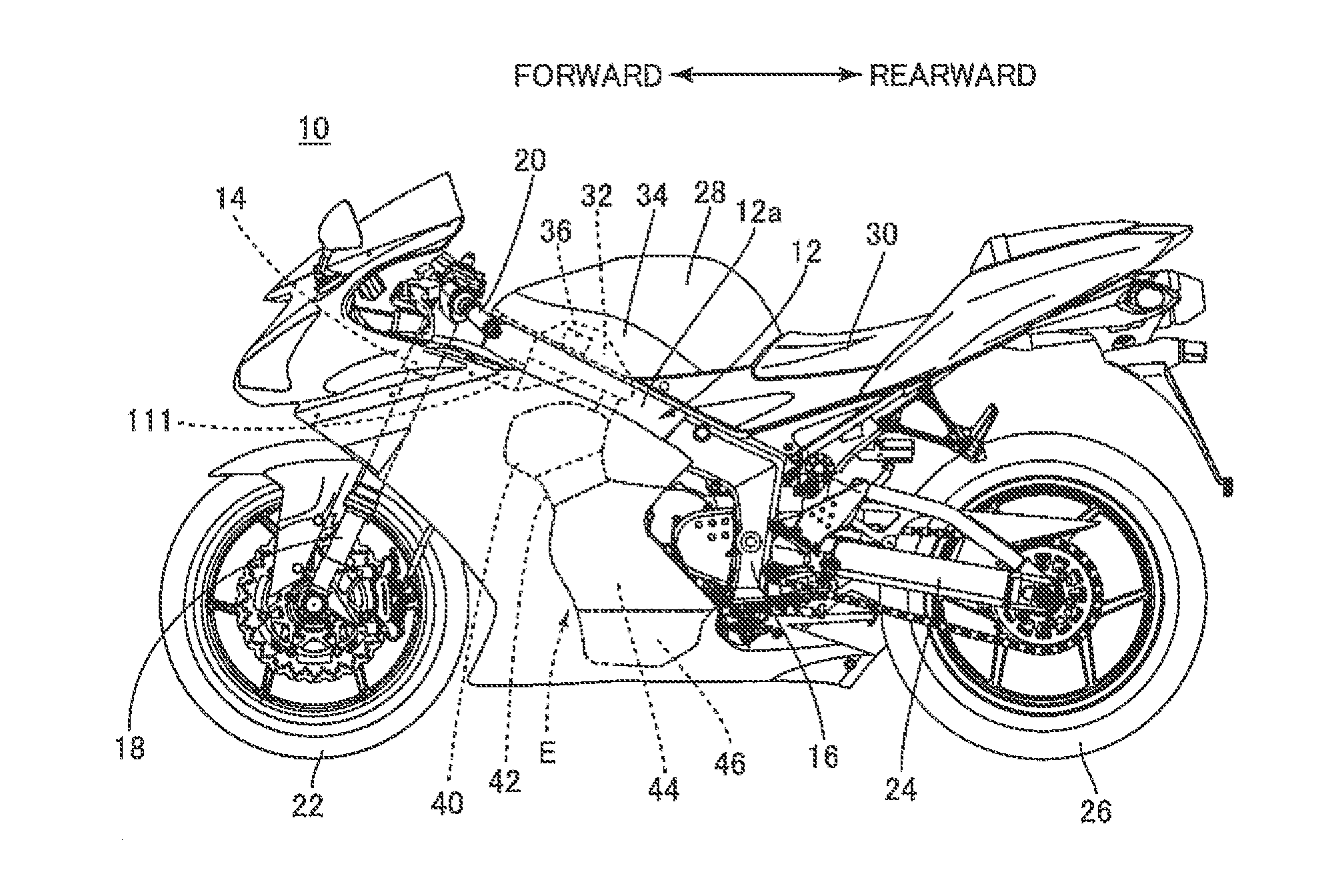
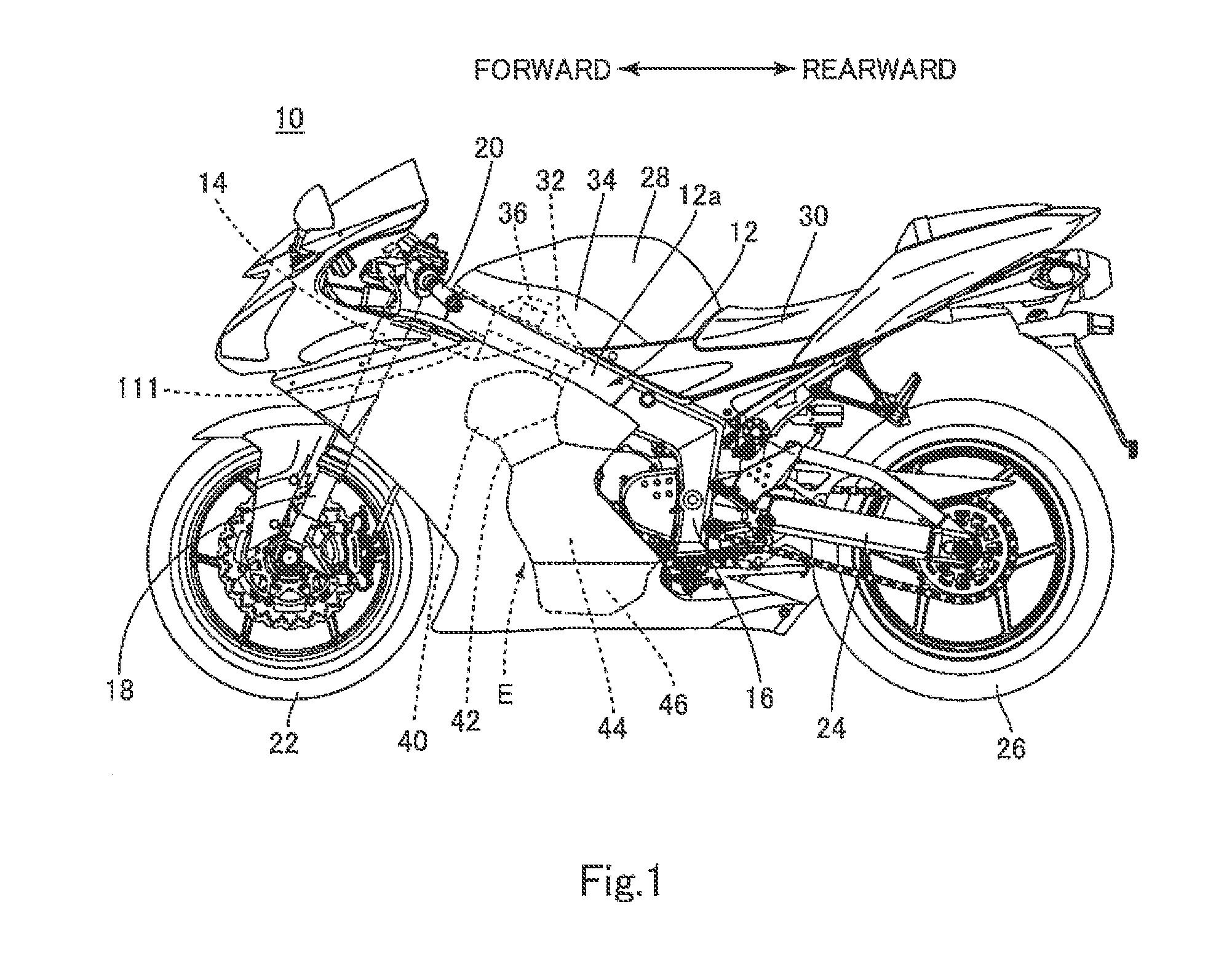
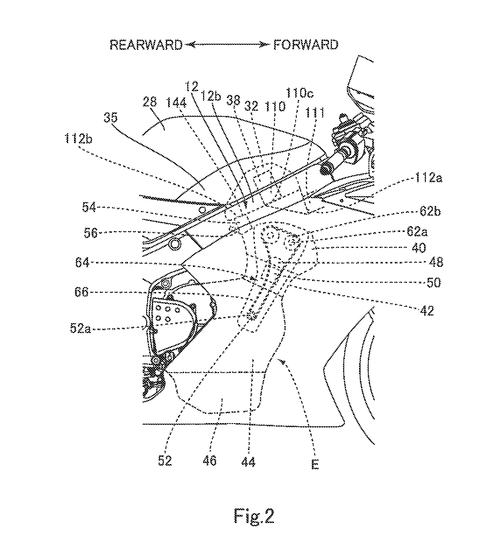
[0075]FIG. 1 is a left side view of a construction of an entire motorcycle 10 which is a straddle-type vehicle according to Embodiment 1. FIG. 2 is an enlarged right side view showing a configuration of an engine E. FIG. 3 is a plan view schematically showing an internal structure of a cylinder head 40, in the motorcycle 10. FIG. 4 is a plan view schematically showing a positional relationship between an air cleaner 32, a relay box 36, and a control unit 38 in the motorcycle 10.
[0076]Referring to FIG. 1, the motorcycle 10 includes a frame 12, a head pipe 14 provided at a front portion of the frame 12, and a pair of right and left pivot frames 16 provided at a rear portion of the frame 12. A steering shaft (not shown) is rotatably inserted into the head pipe 14. A front fork 18 and a handle 20 are attached to the steering shaft. A front wheel 22 is mounted to a lower end portion of the front fork 18. A pair of right and left swing arms 24 is attached to th...
embodiment 2
[0134]Referring to FIG. 13, a motorcycle according to Embodiment 2 includes a control unit case 280 which replaces the control unit case 172 (FIG. 7). The other constituents of the motorcycle are identical to those of the motorcycle 10 of Embodiment 1.
[0135]Like the control unit case 172, the control unit case 280 includes the anti-vibration case 200 and the connector cover 202. At least one groove 282 is formed on an outer surface of at least one of the anti-vibration case 200 and the connector cover 202 to extend along the direction in which the control unit case 280 is inserted into the control unit accommodating member 110. The displacement inhibiting portion 158 passes through the groove 282 when the control unit case 280 is inserted into the control unit accommodating member 110.
[0136]In accordance with this configuration of Embodiment 2, friction resistance between the outer surface of the control unit case 280 and the displacement inhibiting portion 158 can be reduced, which...
embodiment 3
[0137]Referring to FIG. 14, a motorcycle according to Embodiment 3 includes a control unit case 284 which replaces the control unit case 172 (FIG. 7). The other constituents of the motorcycle are identical to those of the motorcycle 10 of Embodiment 1.
[0138]Like the control unit case 172, the control unit case 284 includes the anti-vibration case 200 and the connector cover 202 (not shown). At least one line-shaped protrusion 286 is formed on an outer surface of at least the anti-vibration case 200 to extend along the direction in which the control unit case 284 is inserted into the control unit accommodating member 110. The protrusion 286 is configured to contact an inner surface of the control unit accommodating member 110.
[0139]In accordance with Embodiment 3, the anti-vibration case 200 can be surely fixed inside the control unit accommodating member 110 so that a vibration of the anti-vibration case 200 can be suppressed and a vibration which would be transmitted to the control...
PUM
 Abstract
Description
Claims
Application Information