Supporting structure, keyswitch, and keyboard

a technology of supporting structure and keyswitch, which is applied in the direction of electric switches, contact mechanisms, electrical apparatus, etc., can solve the problems of increasing the cost, reducing the service life of consuming a lot of time and manpower in the assembling or disassembling process, so as to avoid damage to the supporting structure or keyswitch caused by improper force in the man-made assembling process, the effect of simplifying the manufacturing process

Inactive Publication Date: 2011-06-30
DARFON ELECTRONICS CORP
View PDF1 Cites 11 Cited by
  • Summary
  • Abstract
  • Description
  • Claims
  • Application Information

AI Technical Summary

Benefits of technology

[0016]In the prior art, the supporting structure is composed of two supporting member with different shapes. Compared to the prior art, the supporting art of the invention is composed of two supporting member with the same shape, and accordingly, the fabricating processes can be simplified. Besides, the supporting structure of the invention can be assembled by jig. The jig can make the two supporting members to move in parallel, so that a shaft of one supporting member can be obtained in a hole of the other supporting member. Therefore, the damage of the supporting structure or keyswitch caused by improper force in the man-made assembling processes can be avoided. Furthermore, the supporting structure of the invention can rotate more smoothly than that in the prior art.

Problems solved by technology

As described above, the supporting structure 1 needs manpower to be assembled or disassembled, and much time and manpower consume in the assembling or disassembling processes.
Besides, the supporting structure 1 might be damaged by improper force in the assembling processes to increase the cost.

Method used


Image

  • Supporting structure, keyswitch, and keyboard
  • Supporting structure, keyswitch, and keyboard
  • Supporting structure, keyswitch, and keyboard

Examples


Embodiment Construction

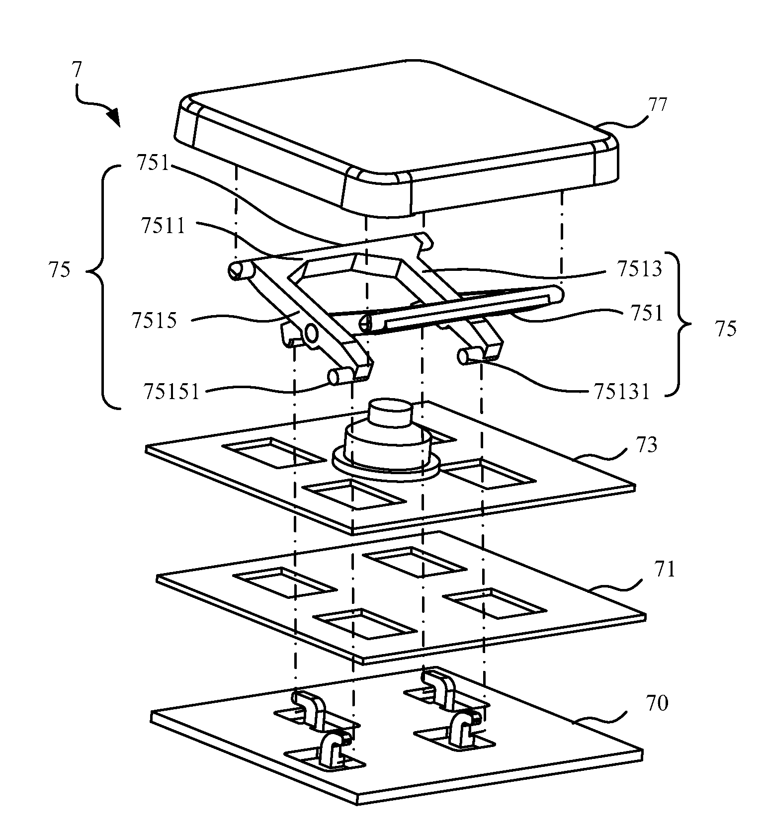
[0029]The invention provides a supporting structure, a keyswitch, and a keyboard using the supporting structure. The supporting structure, which is scissors-type, of the invention can support and connect the keycap of the keyswitch.

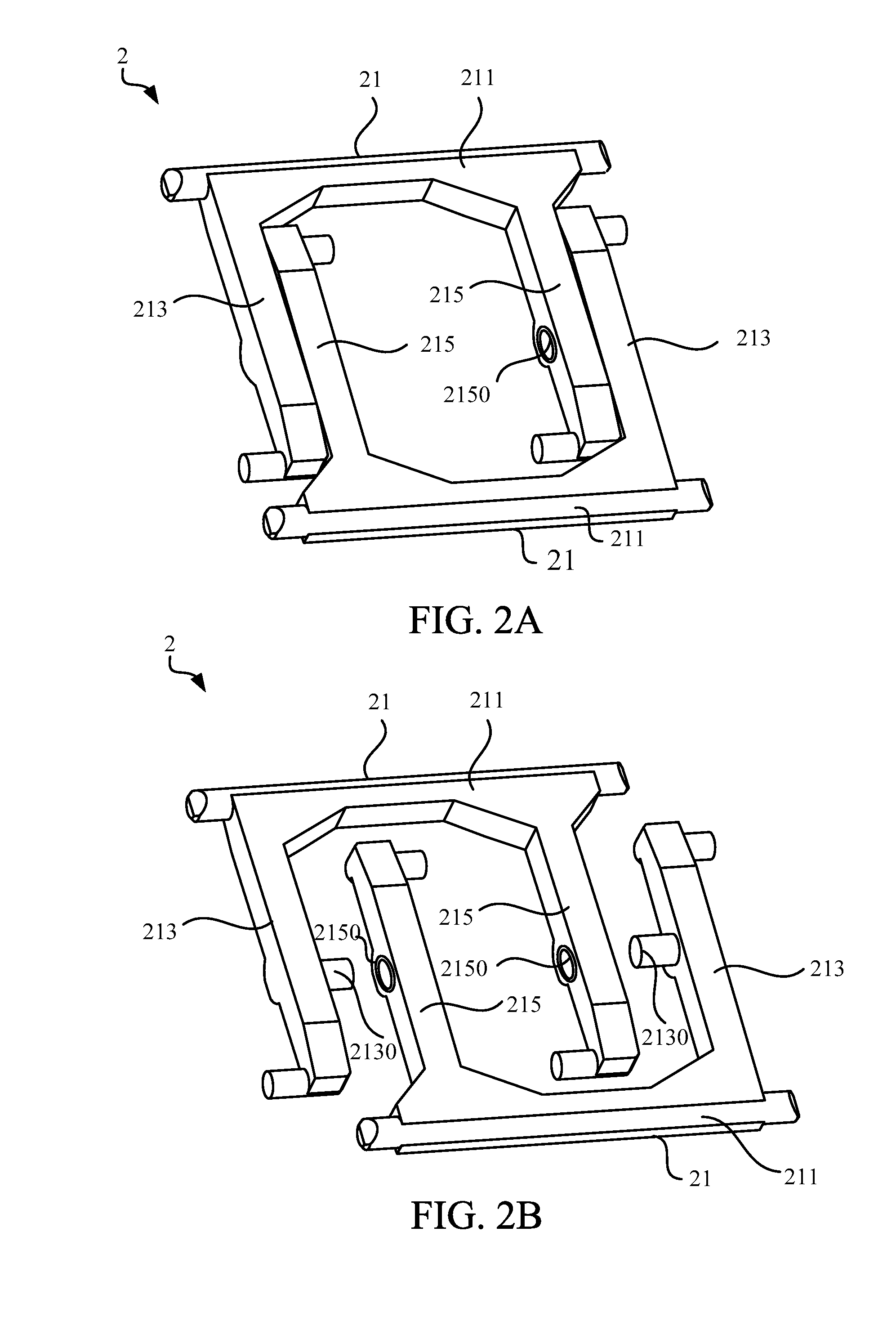
[0030]Please refer to FIG. 2A and FIG. 2B. FIG. 2A is a schematic diagram illustrating a supporting structure 2 according to an embodiment of the invention. FIG. 2B is another schematic diagram illustrating the supporting structure 2 in FIG. 2A. As shown in FIG. 2A and FIG. 2B, the supporting structure 2 in the embodiment includes two supporting member 21 with similar shapes. Each supporting member 21 has a connecting portion 211, a first side arm 213 and a second side arm 215. The first side arm 213 and the second side arm 215 are respectively connected to the connecting portion 211 to make the shape of the supporting member 21 to be similar to a U shape. The first side arm 213 protrudes toward the second side arm 215 to form a shaft 2130, and the positi...


PUM


Abstract

A supporting structure includes two supporting members. Each of the supporting members has a connecting portion, a first side arm, and a second side arm. The first side arm and the second side arm are connected opposite to the connecting portion respectively. The first side arm protrudes to form a shaft and the second side arm forms a hole corresponding to the shaft. The shaft of each of the two supporting members can be rotatable contained in the hole of another supporting member respectively. The shape of the supporting member is similar to a U shape.

Description

BACKGROUND OF THE INVENTION[0001]1. Field of the Invention[0002]The invention relates to supporting structure for connecting and supporting a keycap, and particularly, the invention relates to a novel scissors-type supporting structure and the keyswitch and the keyboard using the same.[0003]2. Description of the Prior Art[0004]For communicating with the computer and executing the functions of the computer, people use various input device, such as keyboard, a mouse, and a touch pen, wherein the keyboard is one of the indispensable devices for operating the computer. Generally, the keyboard comprises a base and a plurality of keyswitch configured on the base. Each keyswitch includes a keycap, a supporting structure, an elastic object, and a switch. The switch is configured on the base to control the delivery of signals. The supporting structure is connected to the base and the keycap for supporting the keycap on the base. The elastic object is configured in the vacant space of the sup...

Claims


Application Information

Patent Timeline
Patent Type & Authority Applications(United States)
IPC IPC(8): H01H13/70H01H13/14
CPCH01H3/125
Inventor WANG, YI-CHEN
Owner DARFON ELECTRONICS CORP
Why Eureka
Try Eureka