Electric rotating machine with cooling mechanism

a cooling mechanism and rotating machine technology, applied in the direction of electrical equipment, dynamo-electric machines, supports/enclosements/casings, etc., can solve the problems of lack of cooling capability, lack of cooling of the coil end as a whole, and failure to drain the coolant from either end, so as to ensure the stability of cooling, enhance the efficiency of cooling the side surface, and discharge a large volume of coolant

Active Publication Date: 2011-06-30
NIPPON SOKEN +2
View PDF12 Cites 27 Cited by
  • Summary
  • Abstract
  • Description
  • Claims
  • Application Information

AI Technical Summary

Benefits of technology

It is another object of the invention to provide an improved structure of an electric rotating machine with a cooling mechanism designed to ensure the cooling ability in supplying coolant to a coil end of a stator of the electric rotating machine even when the electric rotating machine is tilted in a given direction.
The coolant supply cylindrical member may be of a circular or a polygonal shape in transverse cross section. The coolant supply cylindrical member extends substantially parallel to the axis of rotation of the rotor and is disposed adjacent and above the stator in a vertical direction of the electric rotating machine. The first and second coolant outlets create the streams of the coolant which are oriented in directions different from each other, thereby cooling the first and second area of the coil end different in location from each other. This ensures the stability in cooling almost the whole of the coil end even when the electric rotating machine is tilted in a direction in which the rotor turns.
In the preferred mode of the invention, the first and second coolant outlets are located away from each other across a plane extending through a longitudinal center line of the coolant supply cylindrical member and an axial center line of the rotor. In other words, the first and second coolant outlets are located away from each other in a direction perpendicular to the axis of rotation of the rotor. This causes the streams of the coolant to be directed in opposite circumferential directions of the coil end, thereby distributing the coolant almost evenly to the first and second areas of the coil end even when the electric rotating machine is tilted in the direction in which the rotor turns.
The first and second coolant outlets may be located so that a center line passing through a center of an opening of each of the first and second coolant outlets is offset toward a side surface of the coil end from a center line passing through a center of a width of the coil end in an axial line of the coil. In other words, the first and second coolant outlets are located near the side surface of the coil end, thereby discharging a large volume of the coolant to the side surface of the coil end, which enhances the efficiency in cooling the side surface which is usually difficult to cool.
The first coolant outlet is greater in open area from the second coolant outlet. This enables a large volume of the coolant to be emitted to a desired area of the coil end to increase the efficiency in cooling the desired area when the electric rotating machine is titled. The first coolant outlet will preferably be nearer to the top of the coil end than the second coolant outlet when the electric rotating machine is titled.
The coolant supply cylindrical member may include guides, one for each of the first and second coolant outlets. Each of the guide defines a direction in which the coolant is to be emitted from a corresponding one of the first and second coolant outlets. This enhances the accuracy in directing the streams of the coolant to desired areas of the coil end.

Problems solved by technology

When the electric rotating machine is tilted in the above axis-turning direction, it may, therefore, result in a failure in draining the coolant from either of opposed ends of the coolant channel onto a portion of the coil end.
The coolant drops from the cylindrical guides and flows downward along the outer circumferential surface of the coil end and, thus, hardly reaches an outer or an inner surfaces of the coil end which are opposed in the axial direction of the coil end, which may result in a lack in cooling the coil end as a whole.
The above cooling mechanism, therefore, has the problem in that the cooling capability may be deteriorated depending upon a direction in which the electric rotating machine is tilted.

Method used


Image

  • Electric rotating machine with cooling mechanism
  • Electric rotating machine with cooling mechanism
  • Electric rotating machine with cooling mechanism

Examples


first embodiment

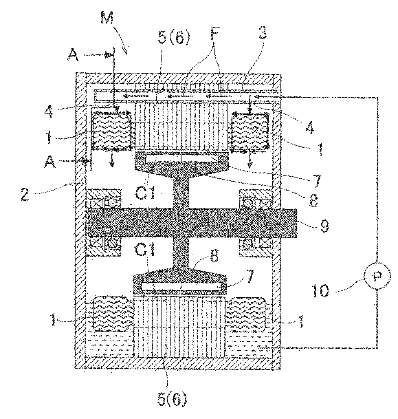
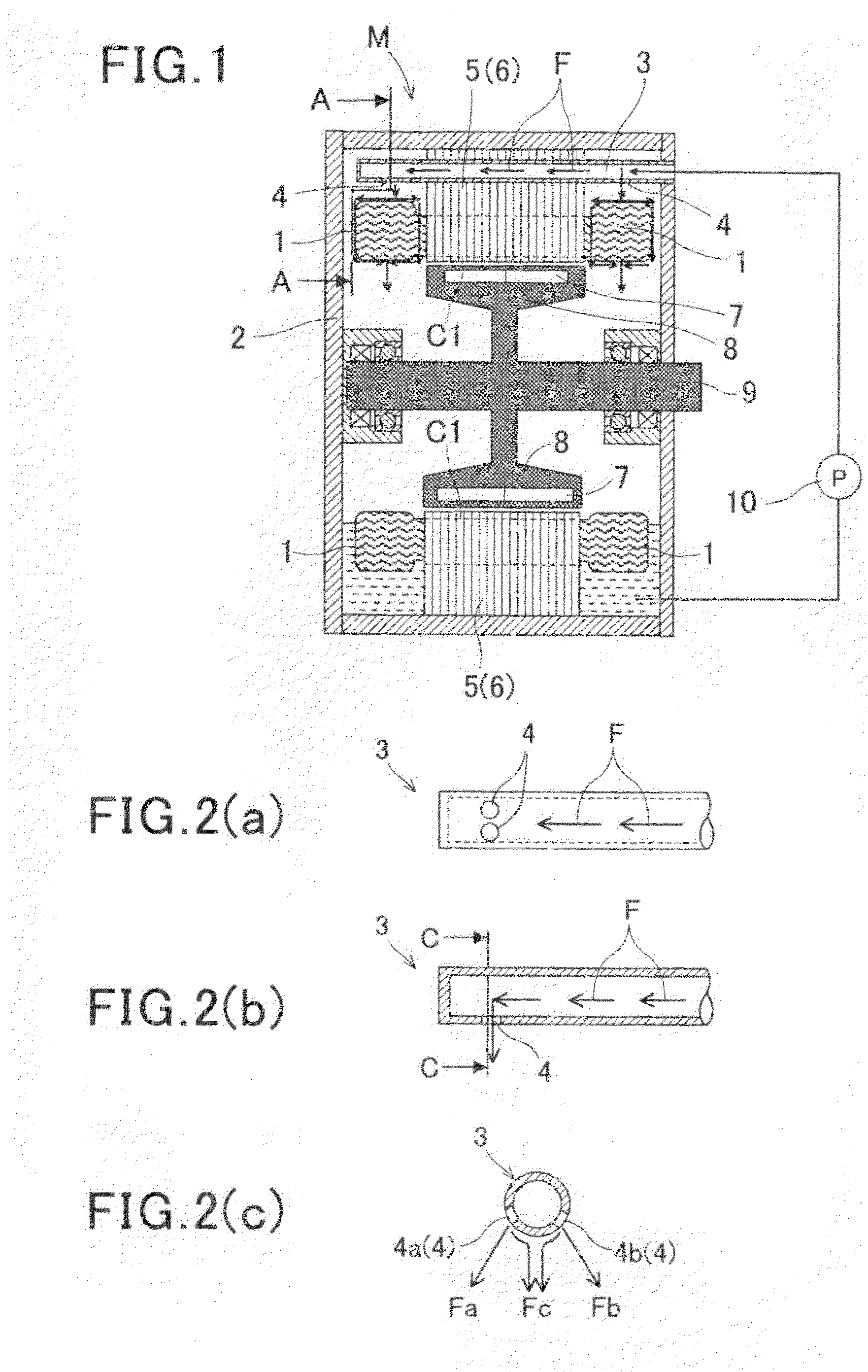
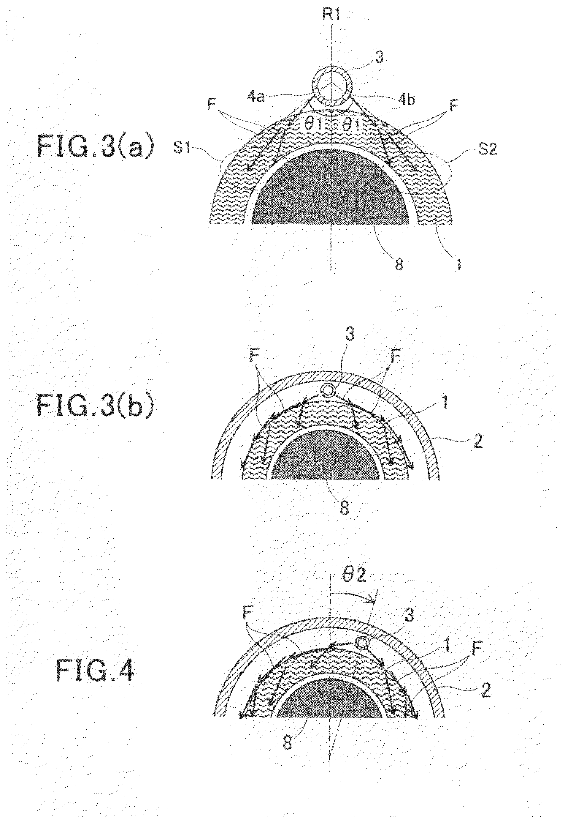
Referring to the drawings, wherein like reference numbers refer to like parts in several views, particularly to FIG. 1, there is shown an electric rotating machine M equipped with a cooling mechanism according to the invention. FIG. 1 is a longitudinal sectional view of the electric rotating machine M, FIG. 2(a) is a partial bottom view which illustrate a coolant supply pipe 3 disposed in the electric rotating machine M of FIG. 1. FIG. 2(b) is a longitudinal sectional view which shows the coolant supply pipe 3. FIG. 2(c) is a transverse sectional view, as taken along the C-C in FIG. 2(b). FIGS. 3(a) and 3(b) are schematically transverse sectional views, as taken along the line A-A in FIG. 1, which illustrate a positional relation between the coolant supply pipe 3 and a coil end 1 and streams of coolant when the electric rotating machine M is placed at a correct orientation, as illustrated in FIG. 1, without being inclined in any direction. FIG. 4 is a transverse sectional view, as t...

third embodiment

In order to alleviate the above drawback, the coolant supply pipe 12 of the third embodiment is so designed as to have the first outlet 4a greater in open area from the second outlet 4b which will be located farther from the vertical center line R1 than the first outlet 4a when the electric rotating machine M is tilted. Specifically, when the electric rotating machine M is tilted in the clockwise direction, as viewed in FIG. 6(b), the amount of the coolant to be discharged per unit time (i.e., the flow rate) from the first outlet 4a will be greater than that from the second outlet 4b. This will cause more amount of the coolant to flow downward over the left portion S3 of the coil end 1, which improves the degree to which the left portion S3 is cooled. The area of the surface of the right portion S4 of the coil end 1 to be cooled, as can be seen in FIG. 6(b), becomes smaller than that before the electric rotating machine M is tilted, thus keeping the degree to which the right portion...

fourth embodiment

The coolant outlets 4 of FIG. 10(a) or 10(b) may be equipped with the cylindrical guides 11 as employed in FIGS. 7(a) to 7(c). The first array and the second array of the outlets 4a and 4b may also be formed to have a locational relation, as illustrated in FIG. 10(c). For example, the outlets 4a correspond to outlets 4d, while the outlets 4b correspond to outlets 4f. The outlets 4d and 4f may also be equipped with the cylindrical guides 11d and 11f, respectively. The directions in which streams of the coolant are to be emitted from the outlets 4a and 4e to the coil end 11 may be altered by changing the orientations of the axes of the cylindrical guides 11c.

Each of the coolant supply pipes 3, 12, 13, and 14 may alternatively be designed to have the coolant outlets 4 whose open area varies as the electric rotating machine M is tilted. This may be achieved by the structure, as illustrated in FIGS. 10(d) to 10(g). The coolant supply pipe 3 of FIGS. 10(d) to 10(g) includes an open area ...


PUM


Abstract

An electric rotating machine includes a rotor, a stator in which a coil is so wound as to have an coil end, and a coolant supply pipe. The coolant supply pipe lies with a length thereof extending substantially parallel to an axis of rotation of the rotor and is disposed above the stator in a direction of gravitational force. The coolant supply pipe has a first and a second coolant outlet through which coolant is to be emitted to the coil end. The first and the second coolant outlets are so oriented as to direct streams of the coolant to a first area and a second area of the coil end which are different in location from each other. This enables the coolant to be emitted to almost the whole of the coil end even when the electric rotating machine is titled in a direction in which the rotor turns.

Description

CROSS REFERENCE TO RELATED DOCUMENTThe present application claims the benefit of priority of Japanese Patent Application No 2009-293043 filed on Dec. 24, 2009, the disclosure of which is incorporated herein by reference.BACKGROUND1. Technical Field of the InventionThe present invention relates generally to an electric rotating machine with a cooling mechanism which is designed to ensure cooling ability in supplying coolant to coil ends of a stator of the electric rotating machine even when the electric rotating machine is tilted in a given direction.2. Background ArtJapanese Patent No. 4167886 teaches a cooling mechanism for cooling coil ends of a stator installed in an electric rotating machine. The cooling mechanism includes arc-shaped coolant channels to which a liquid coolant is fed. Each of the coolant channels has openings formed in a bottom thereof as coolant outlets from which the coolant is drained onto a corresponding one of the coil ends. The coolant channel also has holl...

Claims


Application Information

Patent Timeline
Patent Type & Authority Applications(United States)
IPC IPC(8): H02K9/19
CPCH02K3/24H02K9/00H02K5/20H02K9/19H02K5/203
Inventor MINEMURA, AKITOSHIMATSUI, HIROHITOHAKAMADA, NAOKIONUKI, KAZUYAKOUDA, SHINJIMATSUMOTO, TAKASHI
Owner NIPPON SOKEN
Why Eureka
Try Eureka