Method and Apparatus For Detecting A Multitouch Event In An Optical Touch-Sensitive Device

Active Publication Date: 2011-06-30
BEECHROCK LTD
View PDF67 Cites 99 Cited by
  • Summary
  • Abstract
  • Description
  • Claims
  • Application Information

AI Technical Summary

Benefits of technology

[0053]The invention provides a low cost optical touch o

Problems solved by technology

Over the area of contact, the increase in refractive index will disturb the total internal reflection of the beams within the waveguide.
The disruption of total internal reflection increases the light leakage from the waveguide, attenuating any beams passing through the position of the touch event.
The object must be large enough to detectably attenuate at least one beam in one axis and at l

Method used


Image

  • Method and Apparatus For Detecting A Multitouch Event In An Optical Touch-Sensitive Device
  • Method and Apparatus For Detecting A Multitouch Event In An Optical Touch-Sensitive Device
  • Method and Apparatus For Detecting A Multitouch Event In An Optical Touch-Sensitive Device

Examples


Example

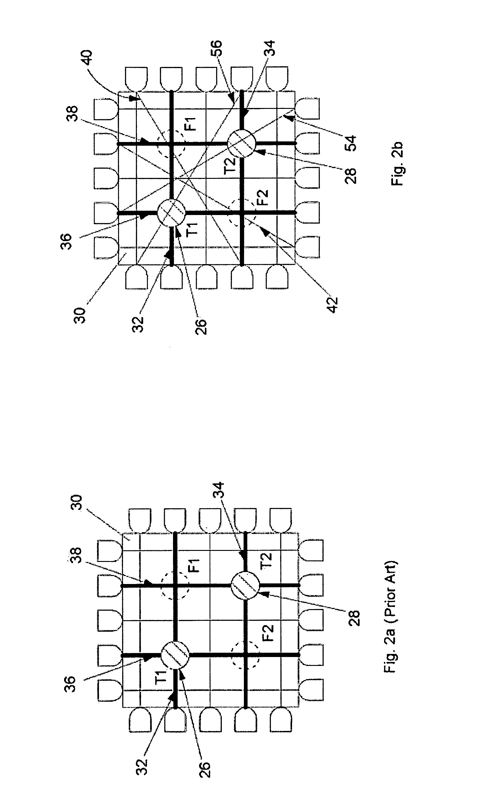
[0074]In the present embodiment, in order to resolve the ambiguity of multiple touches within a touch area, a plurality of beam intersections are tested for interruption, where the tested beams are coincident with, or close to, each indicated candidate touch point. The principle is shown in FIG. 2b, where additional beams 40 and 42, if present, can be used to determine the likelihood of touch events at locations F1 and F2 on the touch sensitive surface 30 of FIG. 2a.

[0075]The beam 40 is near to, and almost coincident with, the intersection of the interrupted beams 32 and 38, so anything other than a very small object present at location F1 will interrupt beams 32, 38 and 40. Similarly, the beam 42 is almost coincident with the intersection of interrupted beams 34 and 36 at location F2. The status of these two additional beams 40 and 42, along with the status of the additional beams 54 and 56 passing through T1 and T2, can be used to determine without ambiguity at which of the locat...


PUM


Abstract

A touch sensitive optical control device comprising a set of light emitters 14, 22 and light detectors 18, 24 arranged relative to a touchable surface 30 such that light transmitted by the emitters is received by the detectors along multiple intersecting beams which pass transversely of the surface and touching the surface at a beam interrupts the light transmitted along the beam. Candidate touch points T1, T2, F1, F2 are defined at the intersections of interrupted beams and are confirmed or not as actual touch points by examining test beams 40, 42, 54, 56 near to or coincident with the candidate touch point.

Description

[0001]The present invention relates to a method and apparatus for detecting a touch point in a touch-sensitive device.BACKGROUND[0002]Referring to FIG. 1, in a conventional optical touch overlay, optical emitters 14, 22 and detectors 18, 24 are arranged along opposite edges of a rectangular touch sensitive surface 16 and an orthogonal grid is formed by the optical beams 12, 20 transmitted between the emitters and the corresponding detectors. As used herein, the term “beam” means the light passing along a narrow optical path between an emitter and a detector, and does not imply that any given emitter necessarily emits light in one or more discrete, directed beams although, in the case of FIG. 1, each emitter only emits light over a narrow angle to ensure that only the directly opposite detector receives light from it. Furthermore, the term “light” includes IR and UV radiation, and the term “optical” is to be interpreted accordingly.[0003]The touch sensitive surface may be an opticall...

Claims


Application Information

Patent Timeline
IPC IPC(8): G06F3/042G06F3/041G06F3/048G06F3/0488
CPCG06F3/0421G06F3/04883G06F2203/04104G06F3/0428G06F3/0418G06F2203/04808G06F3/04166G06F3/04186G06F2203/04108
Inventor DRUMM, OWEN
Owner BEECHROCK LTD
Why Eureka
Try Eureka