Package for an Electrical Device

a technology for electrical devices and packaging, applied in the field of packaging, can solve the problems of known packaging being susceptible to compromising the reliable performance and operational life of supercapacitive elements, and achieve the effect of high compressive forces

Inactive Publication Date: 2011-06-30
CAP XX LTD
View PDF16 Cites 12 Cited by
  • Summary
  • Abstract
  • Description
  • Claims
  • Application Information

AI Technical Summary

Benefits of technology

[0179]The preferred embodiments of the invention provide an hermetic, dimensionally stable package for electrical devices with electrical leads that will be subject to the high temperatures such as during manufacture—for example, during reflow surface mount technology (SMT) assembly into electrical circuits—or high compressive forces during use.

Problems solved by technology

However, the known packaging is susceptible to compromising the reliable performance and operational lifetime of the supercapacitive element due to a lack of practical robustness and security during manufacture and / or subsequent use.

Method used


Image

  • Package for an Electrical Device
  • Package for an Electrical Device
  • Package for an Electrical Device

Examples


example 1

Forming an Hermetic LCP Package

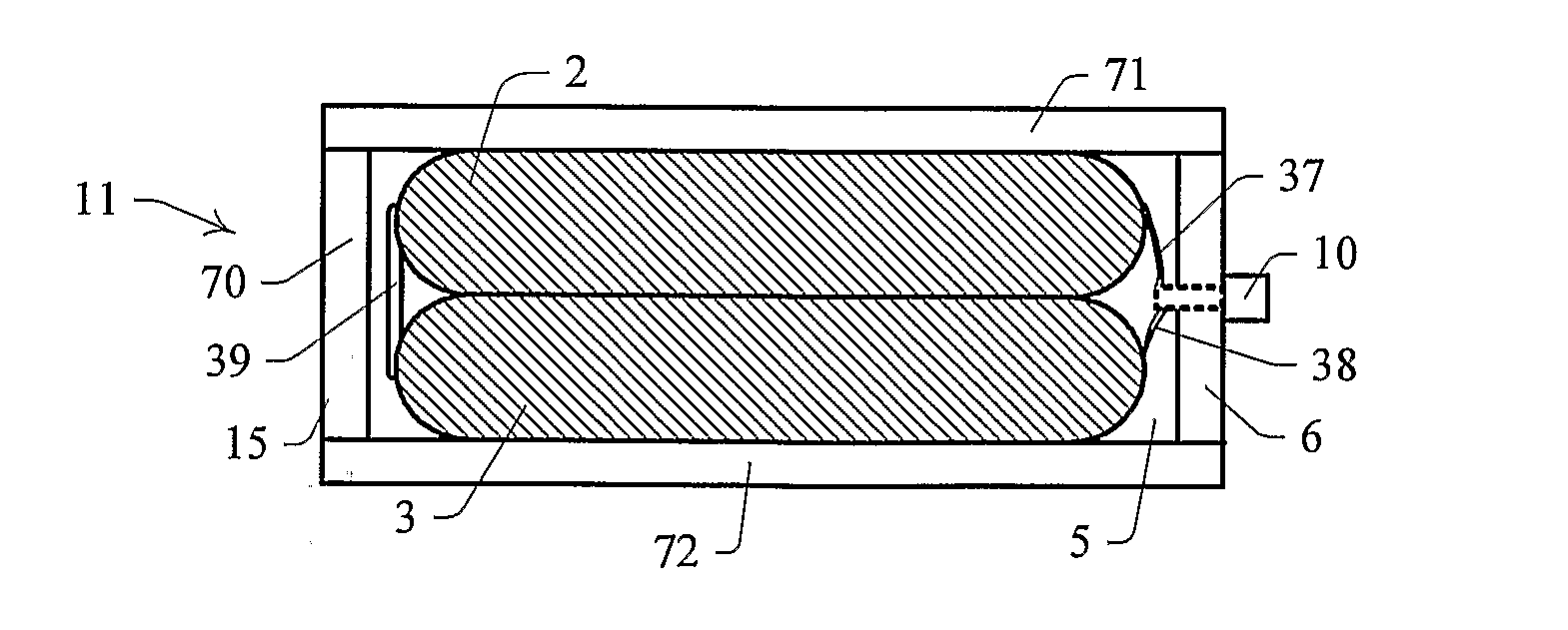
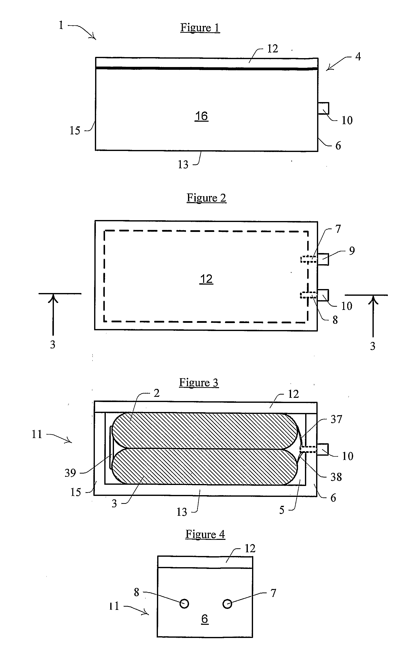
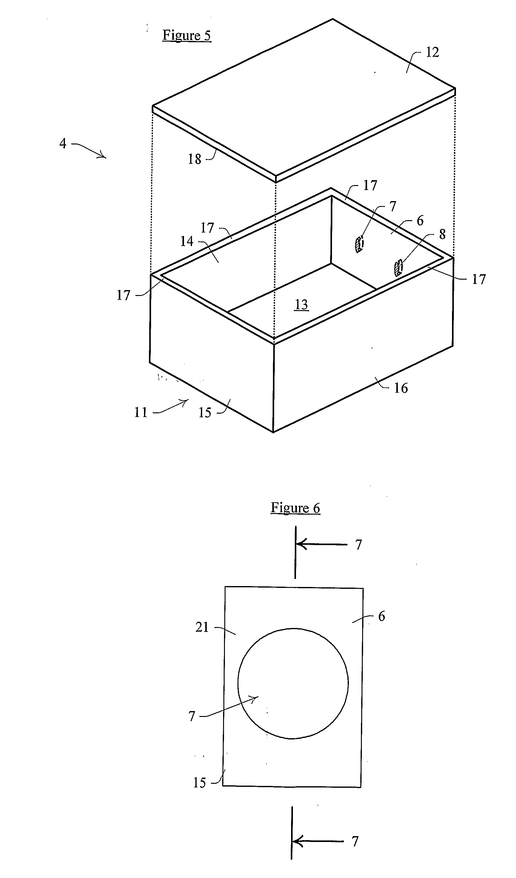
[0342]A 3 mm thick sheet of laminated LCP including alternate sheets of Ultralam® 3850 and Ultralam® 3908 is machined into a 28×20×3 mm open topped housing with a continuous abutment surface about the opening. The internal dimensions of the housing are about 24×16×2 mm. Two like housings are opposed such that the abutment surfaces are presented to each other and then heat sealed together with a 50 μm layer of Ultralam® 3908 captured between them. The seal is created by heating the opposed housings to 290° C. for 30 minutes with a spacer in the heating jaws to prevent over-compression. The package thus formed is cooled to 80° C. before removal from the heat sealer.

example 2

Forming an Hermetic LCP Package

[0343]A 3 mm thick sheet of laminated LCP including alternating sheets of Ultralam® 3850 and Ultralam® 3908 is machined into 28×20×3 mm housing similarly to Example 1. However, the abutment surface is defined by a lip surrounding the open top, where the lip is about 5 mm wide by about 1 mm thick. This provides for maximum external dimensions of about 38×30×3 mm. Two like housings are opposed and heat sealed together with a 50 μm layer of Ultralam® 3908 captured between them. The seal is created by heating the housings to 290° C. for 30 minutes with a spacer in the heating jaws to prevent over-compression. The package thus formed is cooled to 80° C. before removal from the heat sealer.

example 3

Testing the Hermeticity of an LCP Package

[0344]Packages as formed in Examples 1 and 2 were pierced by drilling a 0.5 mm diameter hole through the body of the package into the internal cavity. The cavity was filled with about 0.7 ml of either pure water or dry acetonitrile and the hole sealed by melting a small plug of LCP. The filled packages were then tested for hermeticity by heating to 70° C. and measuring weight loss over several weeks. No weight loss was detectable, verifying that the package thus formed has a permeability of less than 1×10⁻¹³ cm3.cm / cm2 / s / Pa for water vapour and less than 1×10⁻¹⁰ cm3.cm / cm2 / s for liquid acetonitrile.


PUM

PropertyMeasurementUnit
operating voltagesaaaaaaaaaa
thicknessaaaaaaaaaa
thicknessaaaaaaaaaa

Abstract

A supercapacitor (1) includes two like stacked supercapacitive cells (2, 3) that are connected to each other in series. A two-piece generally prismatic sealed package (4) defines an interior (5) to contain cells (2, 3). Package (4) includes a substantially planar access sidewall (6) having two spaced apart apertures (7, 8) extending from interior (5) to an exterior of the package. Sidewall (6) contains a liquid crystal polymer (LCP). A lead assembly, in the form of two spaced apart metal leads (9, 10) are electrically connected to cells (2, 3) respectively, and extend through respective apertures (7, 8) to allow external electrical connection to the cells.

Description

FIELD OF THE INVENTION[0001]The present invention relates to a package and in particular to a package for an electrical device.[0002]The invention has been primarily developed for a supercapacitive device and will be described hereinafter with reference to that application. However, it will be appreciated that the invention is not limited to this particular field of use and, for example, may be used for other electrical devices including energy storage devices such as batteries and capacitors, and other electrical devices such as MEMS electronic devices, MEMS electromechanical devices, MEMS electrochemical devices, integrated circuit devices (IC's), and hybrids of any of the preceding electrical devices, amongst others.BACKGROUND OF THE INVENTION[0003]Any discussion of the prior art throughout the specification should in no way be considered as an admission that such prior art is widely known or forms part of the common general knowledge in the field.[0004]It is known to use liquid ...

Claims


Application Information

Patent Timeline
Patent Type & Authority Applications(United States)
IPC IPC(8): H01G9/155H01G9/145H01M50/209
CPCH01G9/016H01G9/08H01G9/14H01G9/155H01G11/58Y02E60/13H01G11/80H01G11/82H01M2/1061H01M2/1094H01M2/20H01G11/74Y02E60/10H01M50/209H01M50/24Y02P70/50
Inventor AITCHISON, PHILLIP BRETTBILYK, ALEXANDERPERRY, ALLEN DAVIDKUCHARZEWSKI, ANDRZEJ
Owner CAP XX LTD
Why Eureka
Try Eureka