
Strike mechanism for a watch

a technology of a strike mechanism and a watch, which is applied in the direction of electromechanical clocks, timers, and time indications, etc., can solve the problems of reducing the acoustic level of the strike work, wasting kinetic energy, and complicated strike mechanisms, so as to prevent any bouncing and energy waste of the hammer during the strike. , the effect of increasing the acoustic level of the sound

Inactive Publication Date: 2011-06-30
MONTRES BREGUET
View PDF8 Cites 14 Cited by
  • Summary
  • Abstract
  • Description
  • Claims
  • Application Information

AI Technical Summary

Benefits of technology

[0007]It is thus an object of the invention to overcome the drawbacks of the aforementioned prior art by providing a strike mechanism for a watch, which includes means for increasing the acoustic level of the sound produced by at least one gong struck by at least one hammer, while preventing any bouncing and any waste of energy of the hammer during striking.
[0013]wherein the strike mechanism includes a stop member on the path of the drive spring of the hammer in the direction of the gong for increasing the strike speed following contact of one part of the drive spring in action against the stop member.
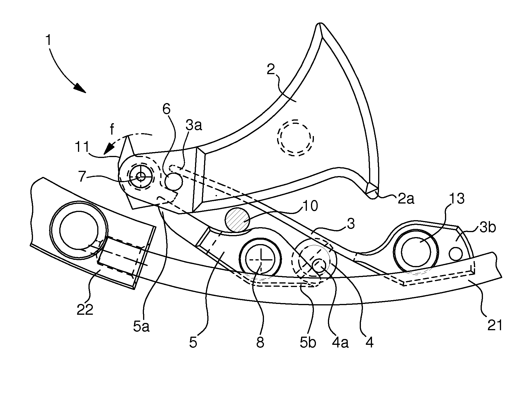
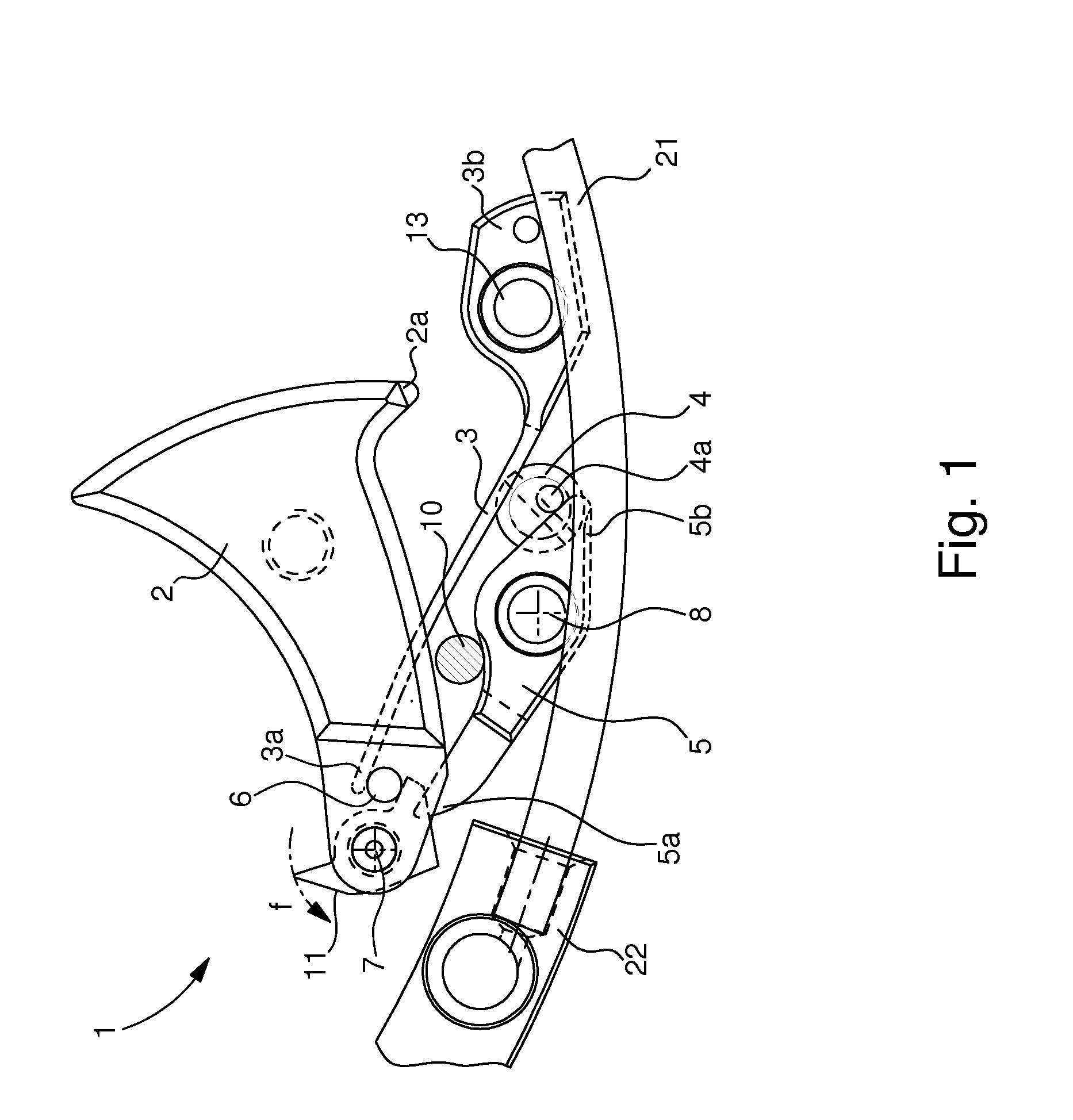
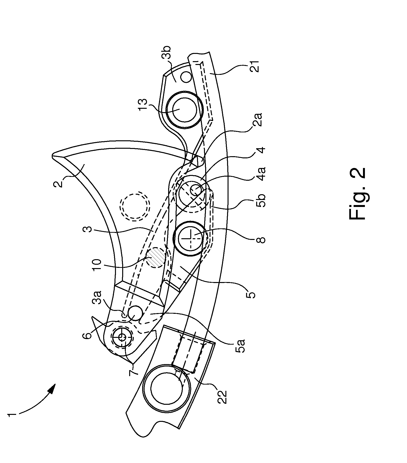
[0015]One advantage of the strike mechanism according to the present invention lies in the fact that at least one stop member is provided on the path of the hammer drive spring when the hammer strikes the gong. This generates a catapult effect of the hammer against the gong at the moment that an intermediate part of the hammer drive spring comes into contact with the the stop member. To achieve this, the drive spring may take the form of a resilient metal strip or beam secured to the watch plate with one end free to push a catch or shaft of the rotating hammer when the hammer strikes the gong. The rotational speed of the end of the spring, which comes into contact with the hammer shaft to drive it against the gong, thus becomes greater after contact with the stop member, than the rotational speed of the end of the spring prior to contact with the stop member, which generates the catapult effect. There is thus less wasted energy from the hammer prior to striking the gong yet there is an increase in the acoustic level generated by the struck gong.
[0016]Another advantage of the strike mechanism lies in the fact that the hammer drive spring can be pre-wound further. This may be achieved without adapting the damping counterspring due to the presence of the stop member on the path of the hammer drive spring when the hammer strikes the gong. The stop member may be connected to the damping counterspring to activate the counterspring with a certain delay compared to the braking of the drive spring upon contact with the stop member. This also makes it easier to move the hammer away after striking the gong to prevent any bouncing.

Problems solved by technology

One drawback of this type of strike mechanism structure with countersprings is that there is a significant waste of kinetic energy from the hammer when the respective gong is struck, which reduces the acoustic level of the strike work.
Moreover, even if the pre-winding of the drive springs is increased, this means adapting the countersprings via their eccentric to prevent any bouncing, which is another drawback of this type of strike mechanism.
However, in order to be able to prevent the hammer wasting energy when it strikes the gong, this hammer arrangement makes the strike mechanism more complicated to make, which is a drawback.
The hammer may bounce against the gong in an undesirable manner during striking, which is another drawback.

Method used


Image

  • Strike mechanism for a watch
  • Strike mechanism for a watch
  • Strike mechanism for a watch

Examples


Embodiment Construction

[0021]In the following description, all those parts of the watch strike mechanism combined with the watch movement that are well known in this technical field will be only briefly described. The emphasis is mainly on the arrangement of the spring elements, including the stop member of the strike mechanism. This stop member guarantees an increase in the strike speed of the hammer with less hammer energy waste, and improved security against any hammer bounce against the gong.

[0022]FIGS. 1 and 2 show a simplified view of a watch strike mechanism 1, whose various parts are mounted in a normal way on a plate, which is not shown to avoid overloading the Figures. This strike mechanism 1 includes at least one gong 21, which is secured at one end thereof to a gong-carrier 22, integral with the watch plate which is not shown. The other end of gong 21, not shown in FIGS. 1 and 2, is generally free to move. Gong 21 may be made in the form of at least one portion of a circle or rectangle. The go...


PUM


Abstract

The strike mechanism (1) of a watch includes a gong (21), which is secured by one end thereof to a gong-carrier (22) integral with a plate, a hammer (2) rotatably mounted on the plate for striking the gong (21) at predetermined times, a damping counterspring (5) for keeping the hammer at a distance from the gong (21) in an idle mode, and a spring (3) for driving the hammer. The drive spring includes one end (3b) secured to the plate and one end (3a) that is free to move. The spring is capable of being wound so that the free end (3a) of the spring drives the hammer (2) against the gong (21) in a strike mode to generate an acoustic sound. The strike mechanism further includes a stop member (10) on the path of the hammer drive spring in the direction of the gong for increasing the strike speed following contact of an intermediate part of the drive spring (3) in action against the stop member.

Description

[0001]This application claims priority from Swiss Patent Application No. 02002 / 09 filed Dec. 24, 2009, the entire disclosure of which is incorporated herein by reference.FIELD OF THE INVENTION[0002]The invention concerns a strike mechanism for a watch. The mechanism includes at least one hammer arranged for striking at least one gong, secured to a gong-carrier, at determined times. Said hammer is held at a distance from the gong by a damping counterspring in an idle mode. A spring driving the hammer of the mechanism can be configured in the form of a resilient strip or beam. This drive spring can be wound to drive said hammer against the gong to provide an acoustic signal, for example of a programmed time period.BACKGROUND OF THE INVENTION[0003]Within the field of watchmaking, a strike mechanism can be combined with a conventional timepiece movement to act as a minute repeater or to indicate a programmed alarm time. This type of strike mechanism generally includes at least one gong ...

Claims


Application Information

Patent Timeline
Patent Type & Authority Applications(United States)
IPC IPC(8): G04B21/00
CPCG04B21/06G04B23/12G04B23/026G04B21/12
Inventor MARECHAL, SYLVAINPESENTI, JEAN-FRANCOISFAVRE, JEROMEKARAPATIS, NAKIS
Owner MONTRES BREGUET
Learn More