Radio resource assignment method and base station device

a radio resource and base station technology, applied in the field of mobile communications technology, can solve the problems of resource exhaustion, low population density, and low number of mobile terminal devices within each cell, and achieve the effect of reducing interference, efficiently and adaptively reducing interferen

Inactive Publication Date: 2011-06-30
HITACHI LTD
View PDF9 Cites 22 Cited by
  • Summary
  • Abstract
  • Description
  • Claims
  • Application Information

AI Technical Summary

Benefits of technology

[0014]The present invention has been made to solve the above problems. It is an object of the present invention to implement fairness for each mobile terminal device at the cell boundary or at the sector boundary by causing peripheral base station devices to offer radio resources to a congested base station in a coordinated manger, and reducing interference.
[0015]It is another object of the present invention to enable the adaptive and efficient reduction of interference by making it possible to automatically change a threshold value for determining whether or not a base station device is congested.
[0016]It is another object of the present invention to reduce interference at the cell boundary and the sector boundary even when congested base station devices adjoin each other by causing the base station devices to coordinate together.
[0022]According to the present invention, interference can be reduced by causing peripheral base station devices to coordinate to offer radio resources to a base station device that is congested due to the wireless communications, thus making it possible to achieve fairness for each mobile terminal device at the cell boundary or at the sector boundary.
[0023]Furthermore, according to the present invention, it is possible to automatically adjust a threshold value for determining whether or not a base station device is congested, thus making it possible to efficiently and adaptively reduce the interference.

Problems solved by technology

In reality, however, the number of mobile terminal devices within each cell is not uniform, substantially varying depending on each cell.
However, in an area somewhat distant from there, population density is not very high.
Due to such a bias, resources will be exhausted in the area where a lot of mobile terminal devices are used, while resources exceed demands in the area where the number of adjacent mobile terminal devices is small.
In addition, at a cell boundary, a decline in throughput is accelerated by interference that takes place because regions overlap one another as described above.

Method used


Image

  • Radio resource assignment method and base station device
  • Radio resource assignment method and base station device
  • Radio resource assignment method and base station device

Examples


embodiment 1

[0067]Embodiment 1 according to the present invention will be hereinafter explained.

[0068]To begin with, the construction of a base station device and operations of each unit of the base station device will be explained.

[0069]FIG. 8 is a diagram illustrating the construction of the base station device.

[0070]First, an antenna (not shown) is connected to the left side of the device depicted in FIG. 8. An analog signal received by the antenna is inputted into an RF (Radio Frequency) unit 201 from the left side of the FIG. 8 and converted into a digital signal. CP (Cyclic Prefix) is extracted from the digital signal by a CP extraction unit 202 at a timing specific to the base station. CP is a certain redundant duration applied to an OFDM (Orthogonal Frequency Division Multiplexing) signal so as to remove multipath interference. The received signal, from which CP is extracted, is multiplied by FFT at a FFT (Fast Fourier Transform) unit 203. A time domain signal is divided into a frequenc...

embodiment 2

[0116]Embodiment 2 will be described below.

[0117]Embodiment 2 according to the present invention will be explained with reference to FIGS. 1, 8, 12, 13, 16 and 17. The explanation of parts identical to those of Embodiment 1 will be omitted.

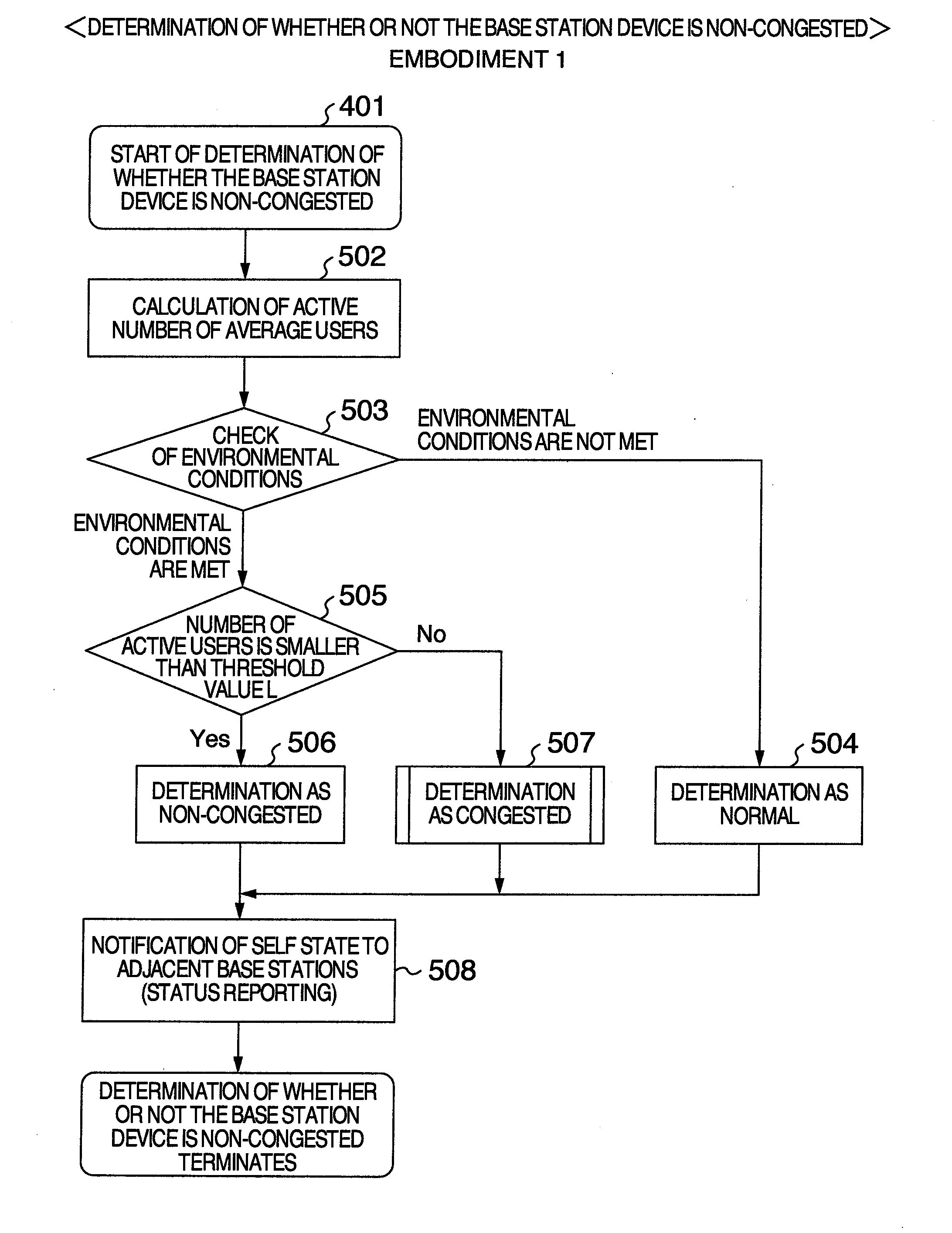
[0118]FIG. 16 is a flow chart illustrating a processing of determining congestion / non-congestion according to Embodiment 2.

[0119]FIG. 17 is a flow chart illustrating a processing of determining whether or not the base station device is congested according to Embodiment 2. According to Embodiment 2, a threshold value for determination of congestion or non-congestion is automatically and adaptively changed.

[0120]Also in Embodiment 2, the determination of congestion or non-congestion, and automatic changing of the threshold value are performed by DSP 215 depicted in FIG. 8. The process shown in FIG. 12 is the same as that according to Embodiment 1. In Embodiment 2, the determination of congestion or non-congestion shown in FIG. 12 is the same as thos...

embodiment 3

[0130]Next, Embodiment 3 will be explained with reference to FIGS. 1, 8, 12, 13, 16, 17, 22, 23, and 24. The explanation of parts identical to those of Embodiment 1 and Embodiment 2 will be omitted.

[0131]In Embodiment 3, when congested base station devices adjoin each other, the base station devices share the resources in a coordinated manner.

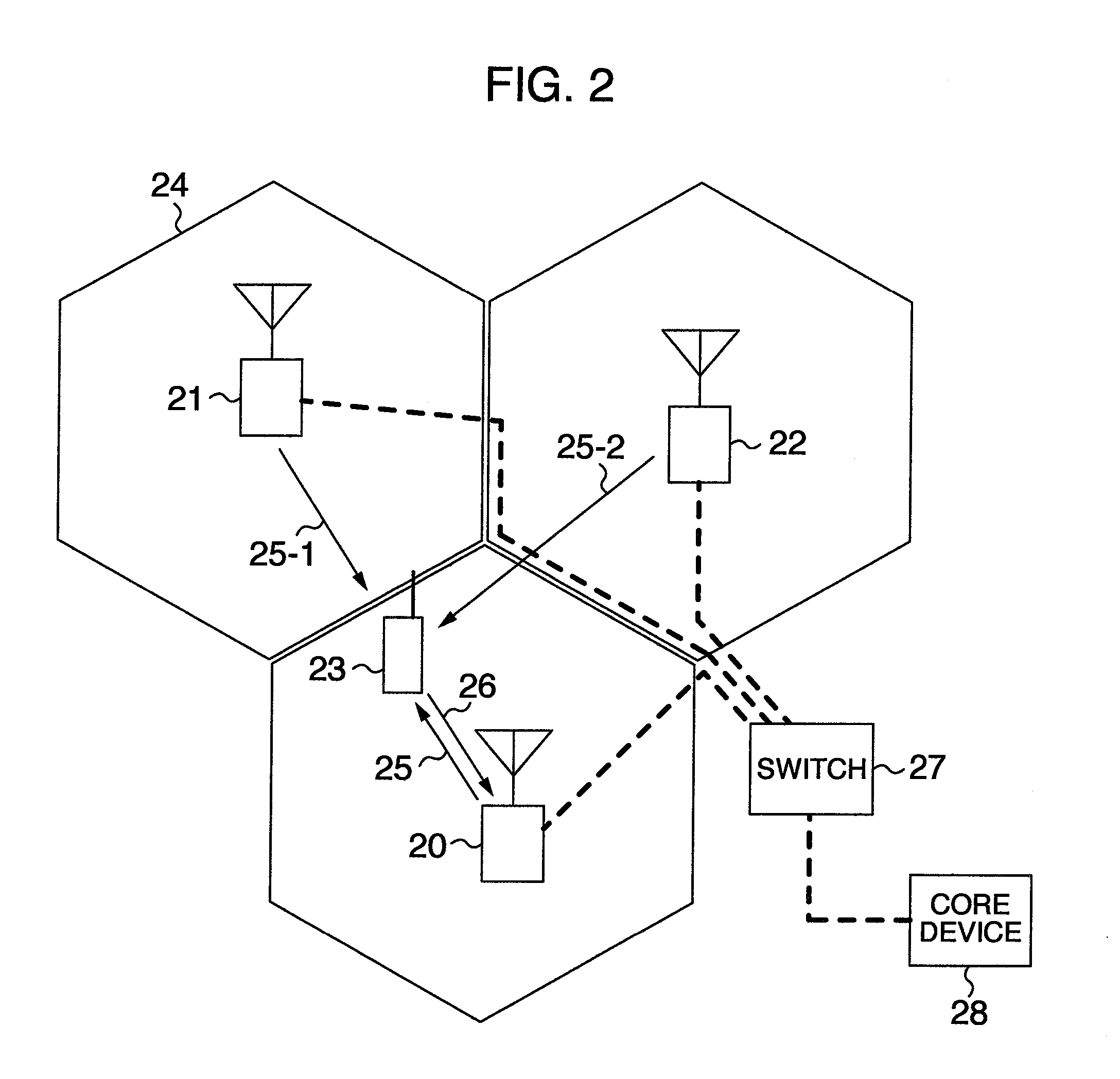
[0132]FIG. 22 is a diagram explaining a relationship among adjacent base stations when Embodiment 3 of the present invention is applied.

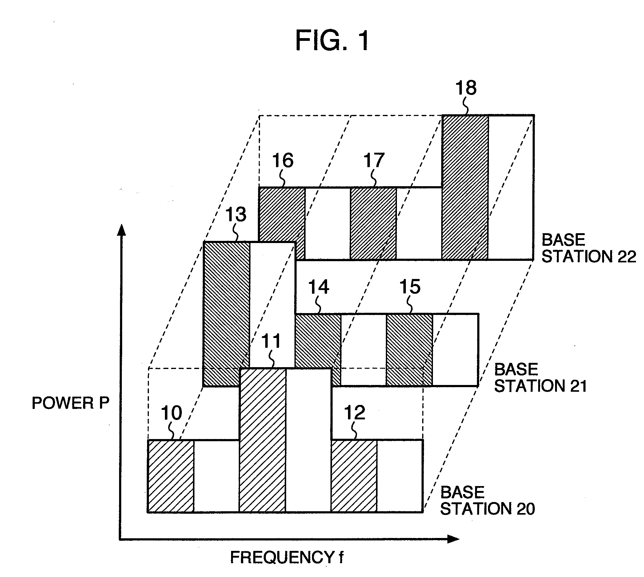
[0133]FIG. 23 is a diagram explaining an example of distribution of frequency resources among adjacent base station devices according to Embodiment 3.

[0134]FIG. 24 is a flow chart explaining the content of the processing in the base station device in Embodiment 3 according to the present invention. In the flow chart, resources are shared by the adjacent base stations in a coordinated manner.

[0135]The processing of Embodiment 3 is also performed by the DSP 215 depicted in FIG. 8.

[0136]The process depicted in FIG...


PUM


Abstract

A radio resource assignment method, wherein it is determined at a predetermined timing whether a cell is congested or not; the determination result is notified to adjacent base stations; results of determination of congestion or non-congestion received from adjacent base stations are stored; when it is determined that the base station is not congested, a check is made whether or not the adjacent base stations are congested; when the adjacent base stations are congested, the use of the resource blocks is restricted to decide an empty resource block; and information on the decided resource block is notified to the adjacent base stations. When it is determined that the base station is congested, the information on the empty resource blocks received from the adjacent base stations is checked, and the empty resource blocks are assigned to mobile terminal devices within the cell.

Description

INCORPORATION BY REFERENCE[0001]The present application claims priority from Japanese application JP 2009-193785 filed on Aug. 25, 2009, the content of which is hereby incorporated by reference into this application.BACKGROUND OF THE INVENTION[0002]The present invention relates to a mobile communications technology. More particularly, the present invention relates to a radio resource assignment technology for preventing interference at a sector boundary or at a cell boundary in a mobile wireless communications system.[0003]As a mobile telecommunications technology advances, a ubiquitous network is expected to be implemented which frees users from restrictions, such as places where they use mobile terminal devices or speed at which they travel, and allows them to connect to a network more freely.[0004]The mobile wireless communications system comprises a plurality of base station devices and a plurality of mobile terminal devices for performing wireless communications with the base s...

Claims


Application Information

Patent Timeline
Patent Type & Authority Applications(United States)
IPC IPC(8): H04W72/04
CPCH04W16/06H04W72/0486H04W72/0426H04W72/27H04W72/52
Inventor KOMAMURA, SHINNOSUKEKUWAHARA, MIKIO
Owner HITACHI LTD
Why Eureka
Try Eureka