Optical device for high quality and compact camera module

a camera module and optical device technology, applied in the field of optical devices for camera modules, can solve the problems of not always possible, undesirable stray light (flare, ghosts), and inability to passively align

Active Publication Date: 2011-06-30
INVENIOS FRANCE SAS
View PDF5 Cites 15 Cited by
  • Summary
  • Abstract
  • Description
  • Claims
  • Application Information

AI Technical Summary

Problems solved by technology

This can involve some constraints on the design of the system itself or can require adding an extra step in the manufacturing process through a centring operation (ex: machining).
Still, this is not always possible, for example due to surface curvatures of lenses that might be not adapted to perform accurate centring.
Also, the lens stack obtained from that kind of passive alignment can present undesirable stray light (flare, ghosts).
In some cases, passive alignment is not possible and active alignment is needed that definitely adds a long step to the process and brings the final cost up.
Moreover, in a mobile phone camera, the space to integrate a camera module is very limited and there is no easy way to integrate a liquid lens in a lens barrel of such camera module.
However, the entire mechanical datum of the lens to be aligned (by centring) with respect to other lenses is not always available, or the optical axis of the lens to be aligned is not well aligned with respect to its mechanical datum (i.e., its outer diameter OD) during the manufacturing process.
Flexible Printed Circuit (FPC) gluing could be a solution, however this solution requires a double tape conductive glue / tape that are known to be not reliable and to create contact failure during the assembly process.
Other solutions such as spring metal solutions described in EP1992968 could be used and are more reliable than a FPC gluing, however the pressure applied through the metal spring contact can modify the position of the liquid lens, and thus deteriorate the optical alignment of the liquid lens and the optical elements.
Experience has shown that to get very accurate Glass moulded with Datum B below 15 μm, the production yield is ranging around 80% with a very poor reliability performances.

Method used


Image

  • Optical device for high quality and compact camera module
  • Optical device for high quality and compact camera module
  • Optical device for high quality and compact camera module

Examples


Embodiment Construction

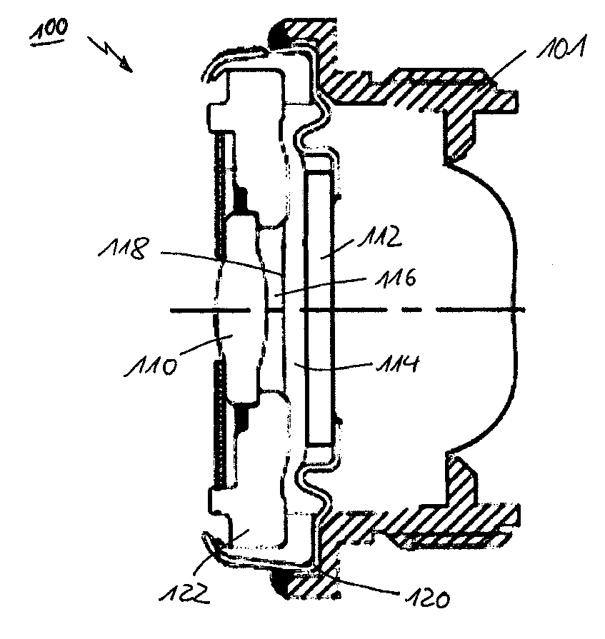
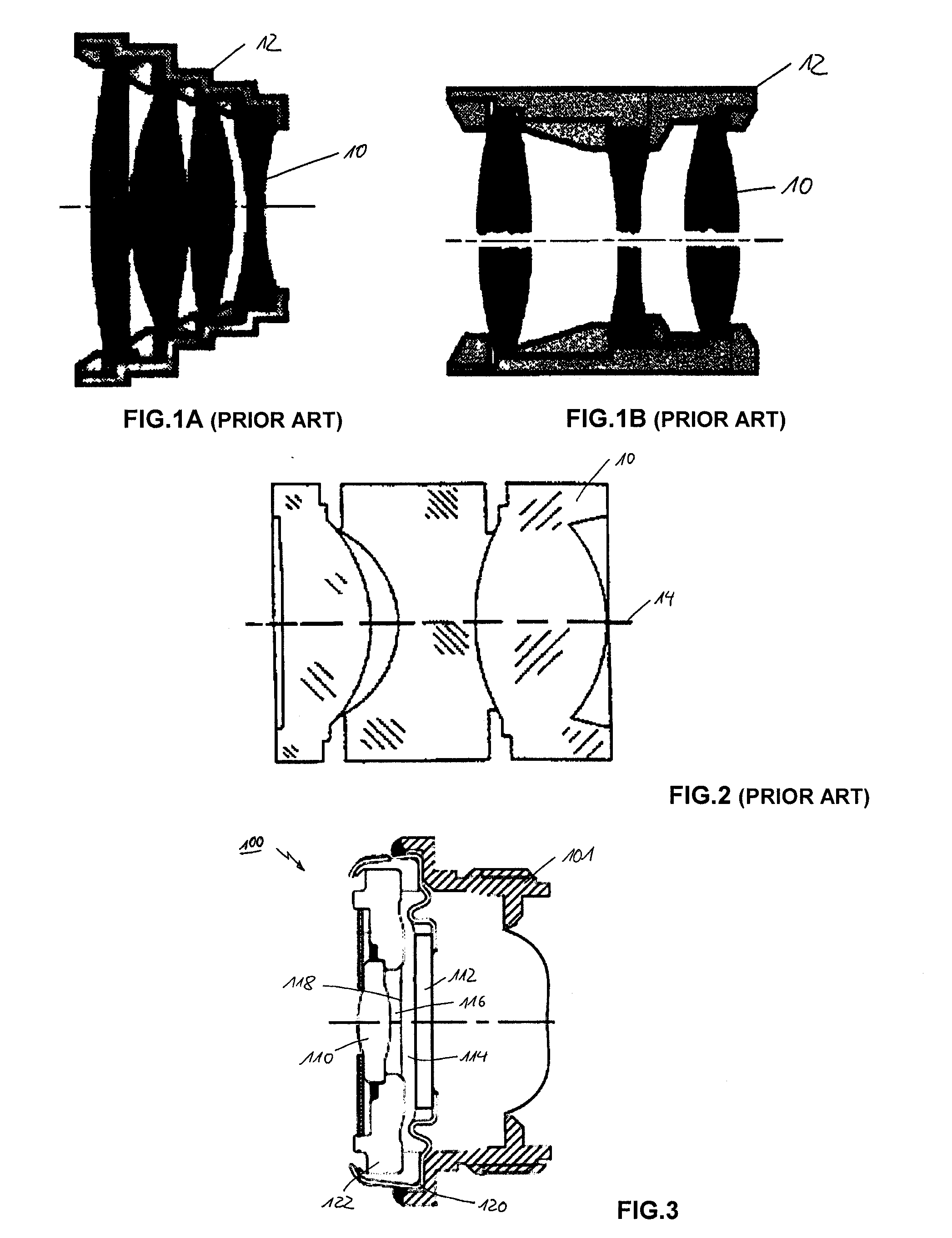
[0037]The present invention related to an optical device comprising a liquid lens having at least one fixed lens and a liquid lens holder wherein accurate datum of the liquid lens can be used in order to avoid at least partially active alignment process and ensure the best image quality (highest MTF) of the imaging device that integrate the optical device.

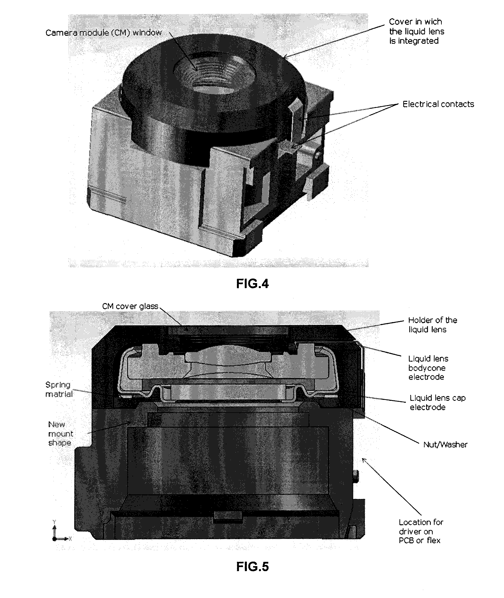
[0038]According to one embodiment of the invention, the flat flange glass molded lens (Z1 of FIG. 13) and its outer diameter can be used as reference on which the liquid lens holder may be centered (according to X and Y axis) and positioned according to a Z axis. In one example, the inner diameter of the liquid lens holder could be used as reference for centering with the other parts of the lens as well as the flat reference of the liquid lens holder bottom for accurate Z position. For easiness of integration that liquid lens holder will integrate at least one electrical contact for contacting one electrode of the liquid lens. Such...


PUM


Abstract

An optical device for a lens assembly of a camera module is disclosed. The optical device includes a liquid lens having at least one fixed lens and a transparent window, facing each other and delimiting, at least in part, an internal volume containing two immiscible liquids having different optical indices, and a first and a second electrode. The liquids form an interface moveable by application of a voltage between said electrodes. The optical device also includes a liquid lens holder, wherein the liquid lens holder has at least one electrical contact for contacting one electrode of the liquid lens, and at least one Z reference datum for aligning the fixed lens of the liquid lens with other optical elements of the lens assembly.

Description

TECHNICAL FIELD OF THE INVENTION[0001]The invention relates to an optical device for a camera module, and more particularly an optical device comprising a liquid lens with a fixed lens and a liquid lens holder adapted for centring the liquid lens with other fixed lenses of a camera module.BACKGROUND OF THE INVENTION[0002]Optical industry and optical manufacturers commonly use the outer diameter (OD) of lenses to align them with an accuracy of a few μm (3-10 μm). Centring a stack of lenses is performed via an accurate mechanical datum that is built in the lens barrel. This is a very cost effective solution. The method is applied, for example, for aligning lenses of an imaging system. The imaging system may be, for example, part of a mobile phone. The approach of passive lens alignment implies that:all lenses have been manufactured in order to align within a few μm (2-5 μm) the optical axis with respect to the OD of the lenses. This can involve some constraints on the design of the sy...

Claims


Application Information

Patent Timeline
Patent Type & Authority Applications(United States)
IPC IPC(8): G03B17/00G02B3/12
CPCG02B3/14H01L27/14618G03B17/12H01L2924/0002H01L2924/00
Inventor CRAEN, PIERREBOULIN, YVES-SEBASTIENFULLER, PAUL
Owner INVENIOS FRANCE SAS
Why Eureka
Try Eureka