Positioning method for orthodontic appliance and structure thereof

a technology of orthodontic appliances and positioning methods, applied in the field of positioning methods for orthodontic appliances and their structure, can solve the problems of increasing the economic burden on patients, poor efficiency, and relatively high fitting costs, and achieve the effect of reducing the fitting cos

Active Publication Date: 2011-06-30
EZBOND DIGITAL CO LTD
View PDF10 Cites 50 Cited by
  • Summary
  • Abstract
  • Description
  • Claims
  • Application Information

AI Technical Summary

Benefits of technology

[0012]A primary objective of the present invention is to provide a positioning method for orthodontic appliance and structure thereof, enabling fitting of the orthodontic appliance to be more convenient and more efficient, thereby reducing cost of fitting.
[0013]The aforementioned positioning method for orthodontic appliance uses base units molded by plastic injection, and during the fabricating process, a crossed reference line is first drawn on a dental mold of the patient, after heating, the orthodontic appliance is embedded to the base unit, and a flexible member is used to bind and fixedly position the orthodontic appliance. Each of the aforementioned base units together with the orthodontic appliance thereof is attached to the dental mold, and after appropriately adjusting the positions of the orthodontic appliances, light curing composite resin is attached to each of the base units, enabling the light curing composite resin to mutually connect each of the base units. Accordingly, after applying an adhesive layer to each of the orthodontic appliances, each of the series connected base units together with the orthodontic appliances bound to the base units is directly attached to the respective teeth portion of the patient requiring straightening, thereby enabling fitting of orthodontic appliances to be more convenient and providing a more efficient fabricating process.

Problems solved by technology

The aforementioned fitting method of orthodontic appliances of the prior art can only be used according to the teeth of an individual patient; moreover, a professional dental lab technician must match up and fabricate the basic units, and the entire fabricating and fitting process is labor intensive and time consuming, efficiency is poor, and cost of fitting is relatively high, thus increasing the economic burden on the patient.

Method used


Image

  • Positioning method for orthodontic appliance and structure thereof
  • Positioning method for orthodontic appliance and structure thereof
  • Positioning method for orthodontic appliance and structure thereof

Examples


Embodiment Construction

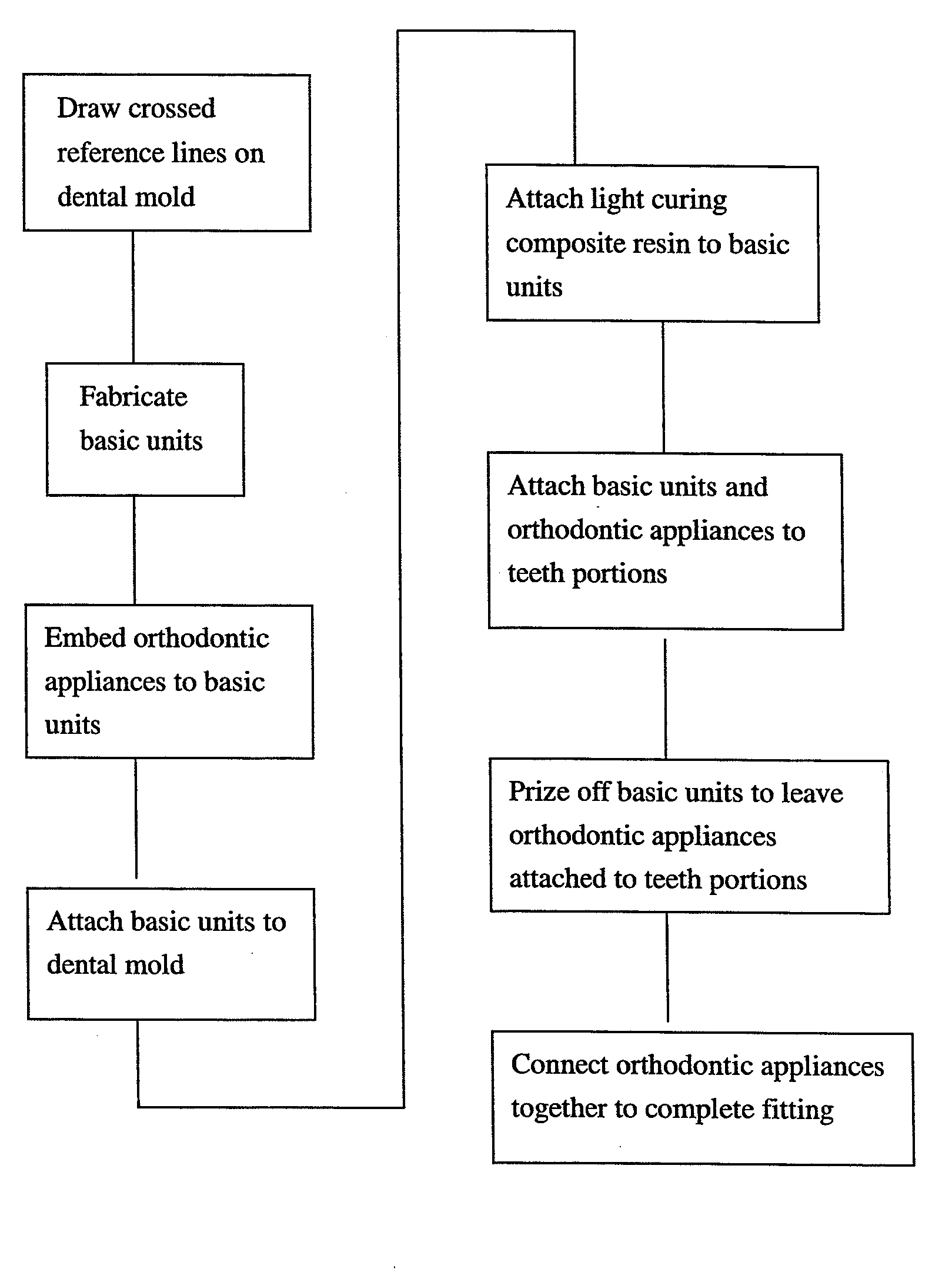
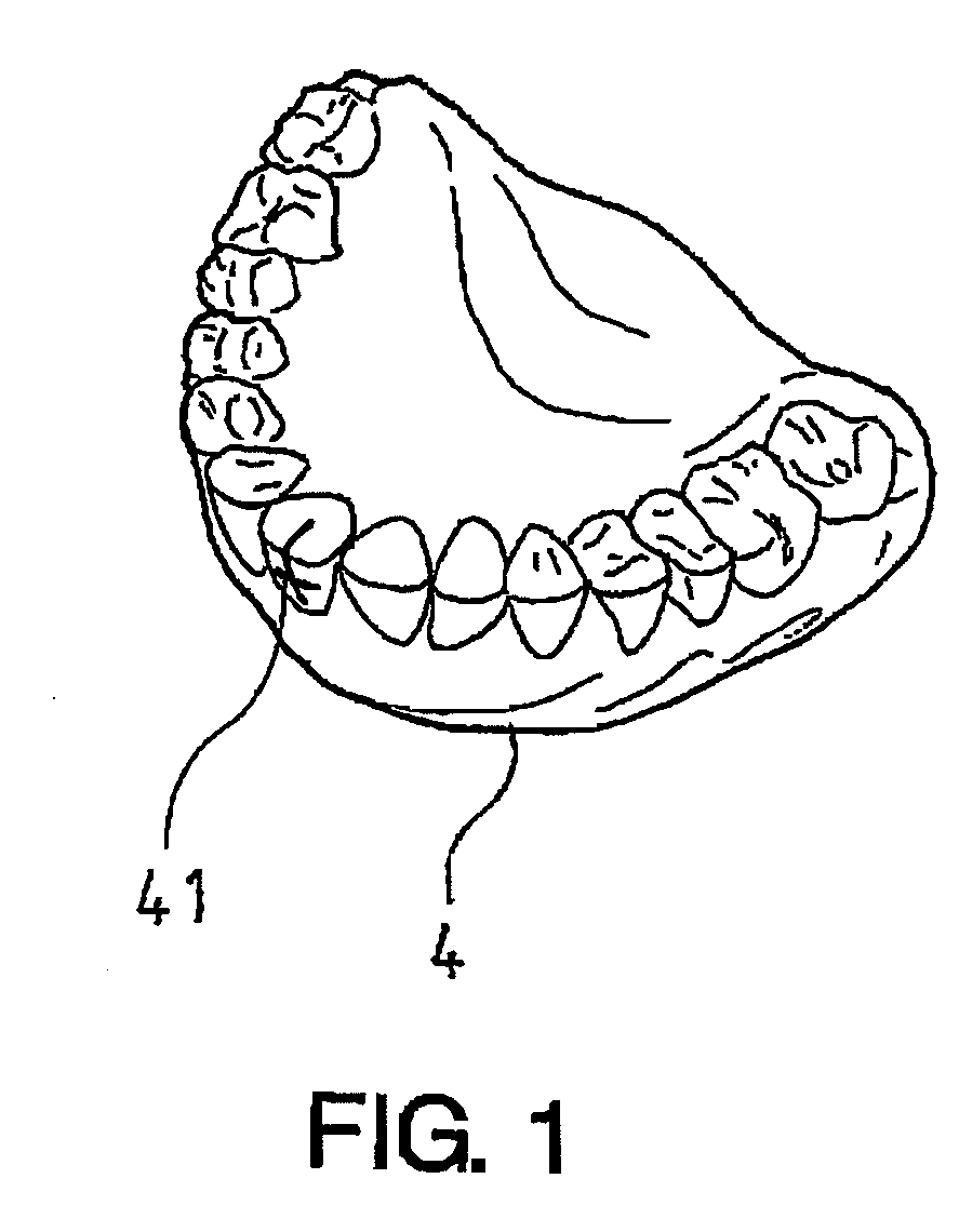
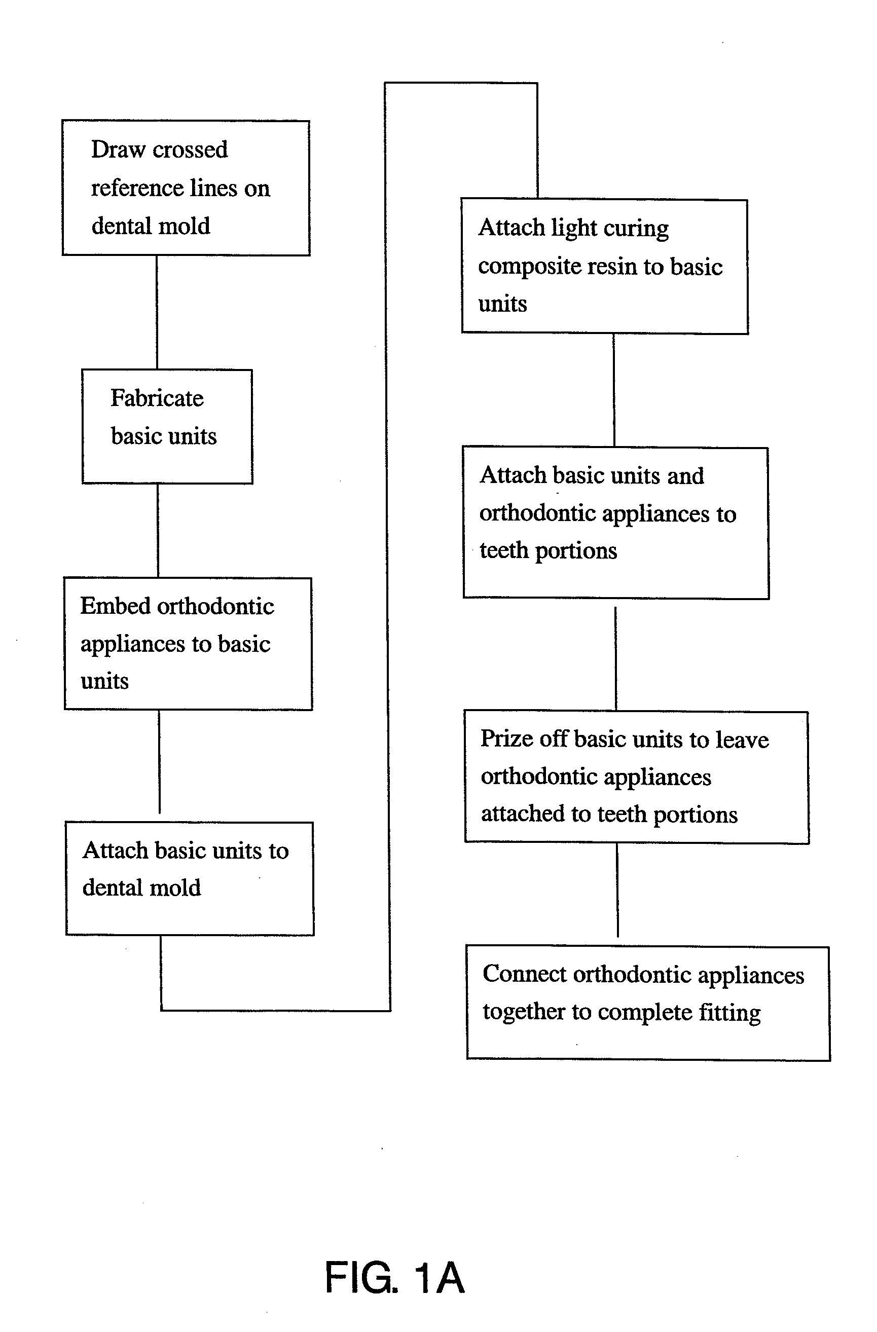
[0024]Referring together to FIG. 1 and FIGS. 1A to FIG. 7, which show the entire fabricating and fitting process of the present invention, primarily comprising the following steps:

[0025]1. Fabricating a dental mold 4 according to the dental profile of the patient, and drawing crossed reference lines 41 on the dental mold 4 of the patient (see FIG. 1) using a specific instrument.

[0026]2. Fabricating different base units 1 using plastic injection molding means based on different teeth portions and different forms of orthodontic appliance, wherein each of the base units 1 comprises a horizontal hook portion 11 and a vertical portion 12 extending downward from the horizontal hook portion 11. In which the vertical portion 12 is provided with a transverse positioning channel 121 at an appropriate position thereof, and a vertical alignment groove 122 is provided in a central position of the vertical portion 12, thereby forming crossed reference lines. (see FIG. 2).

[0027]3. Allocating the v...


PUM


Abstract

A positioning method for orthodontic appliance and structure, mainly provided with base units molded by plastic injection. During the fabricating process, a crossed reference line is first drawn on a dental mold of the patient, after heating, the orthodontic appliance is embedded to the base unit, and a flexible member is used to bind and fixedly position the orthodontic appliance. Each of the aforementioned base units together with the orthodontic appliance is attached to the dental mold, and then light curing composite resin is attached to each of the base units. Accordingly, after applying an adhesive layer to each of the orthodontic appliances, each of the series connected base units together with the orthodontic appliances bound to the base units is directly attached to the respective teeth portion of the patient requiring straightening, thereby enabling fitting of orthodontic appliances to be more convenient and providing a more efficient fabricating process.

Description

BACKGROUND OF THE INVENTION[0001](a) Field of the Invention[0002]The present invention relates to a positioning method for orthodontic appliance and structure thereof, and more particularly to a positioning method and structure which enables fitting of orthodontic appliances to be more convenient and more efficient, thereby reducing fitting cost.[0003](b) Description of the Prior Art[0004]In general, when straightening crooked teeth, orthodontic appliances are normally attached to the surfaces the teeth, after which each of the orthodontic appliances are tightly connected. Traditional fitting methods of orthodontic appliances roughly follow the following steps:[0005]1. First fabricating a dental mold according to the condition of the teeth of the patient.[0006]2. Drawing a cross line on the dental mold, and coating the inner edge with wax material.[0007]3. Aligning the orthodontic appliance with the inner edge of the dental mold according to the cross line, and then forming a basic ...

Claims


Application Information

Patent Timeline
Patent Type & Authority Applications(United States)
IPC IPC(8): A61C7/00
CPCA61C7/146
Inventor HUANG, CHENG-HO
Owner EZBOND DIGITAL CO LTD
Why Eureka
Try Eureka