
Wireless Location-Based System for Detecting Hazardous Conditions

a location-based system and hazardous conditions technology, applied in the field of sensing devices, can solve the problems of expensive wiring, inability to adapt to changing conditions, and the type of system is not portable or adaptable to changing conditions,

Active Publication Date: 2011-06-30
HONEYWELL INT INC
View PDF11 Cites 33 Cited by
  • Summary
  • Abstract
  • Description
  • Claims
  • Application Information

AI Technical Summary

Problems solved by technology

Such gas detection systems may further alert an operator so that an action may be taken to preclude a potentially harmful result within the plant.
While such systems are effective in fixed locations, such as when located near industrial equipment in an industrial plant, these types of systems are not portable or adaptable to changing conditions.
Additionally, such conventional gas detection systems typically do not provide quick centralized access to information regarding gas detection events, including the location of the event(s) and location-based gas detection historical information.
Further, if the conventional system does provide centralized access, expensive wiring is required to connect the gas detectors to the central station.
A central station operator, however, does not have access to location information and the gas concentration information as a function of time is not available until a much later time, when the device's daily log may be transferred to a personal computer.

Method used


Image

  • Wireless Location-Based System for Detecting Hazardous Conditions
  • Wireless Location-Based System for Detecting Hazardous Conditions

Examples


Embodiment Construction

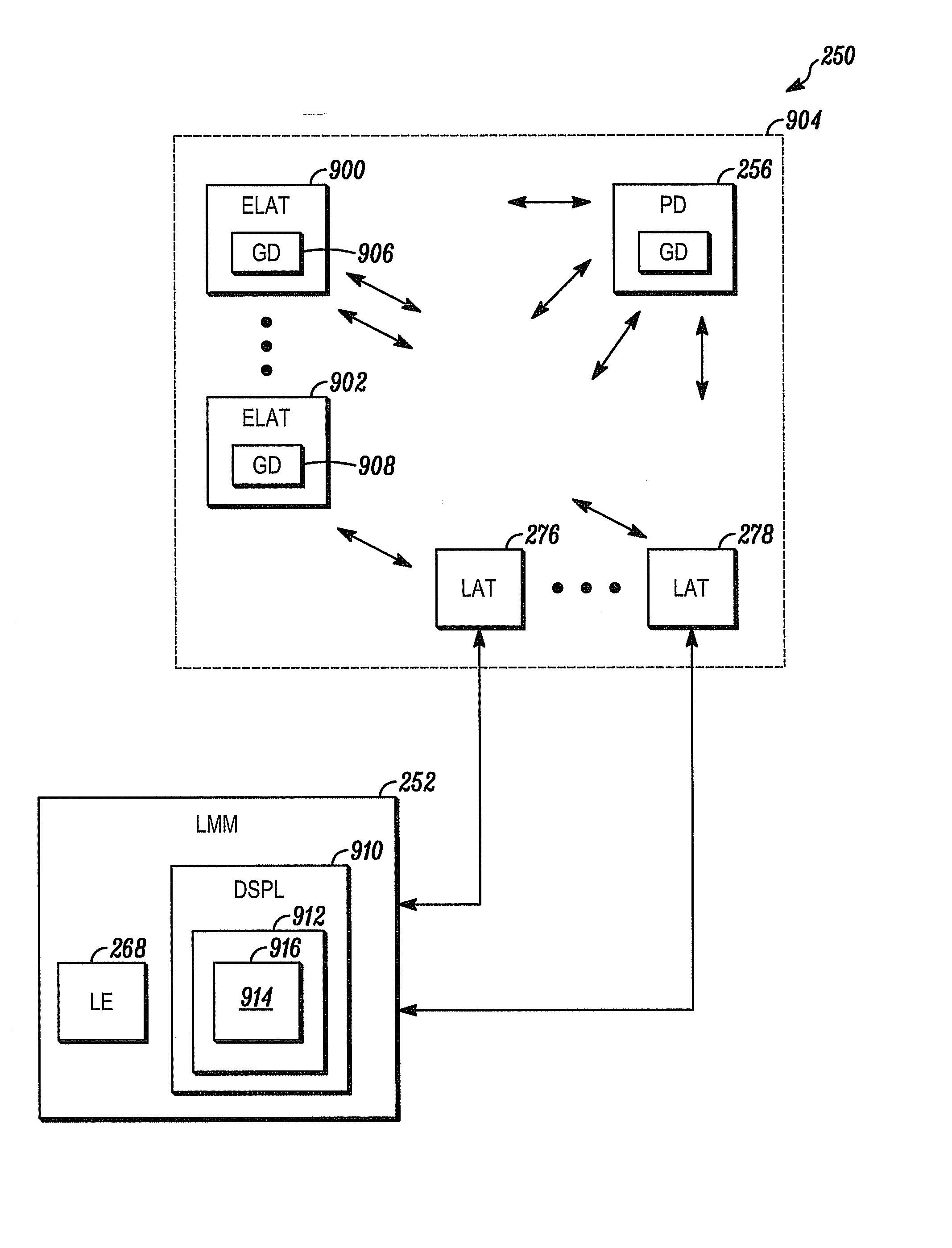
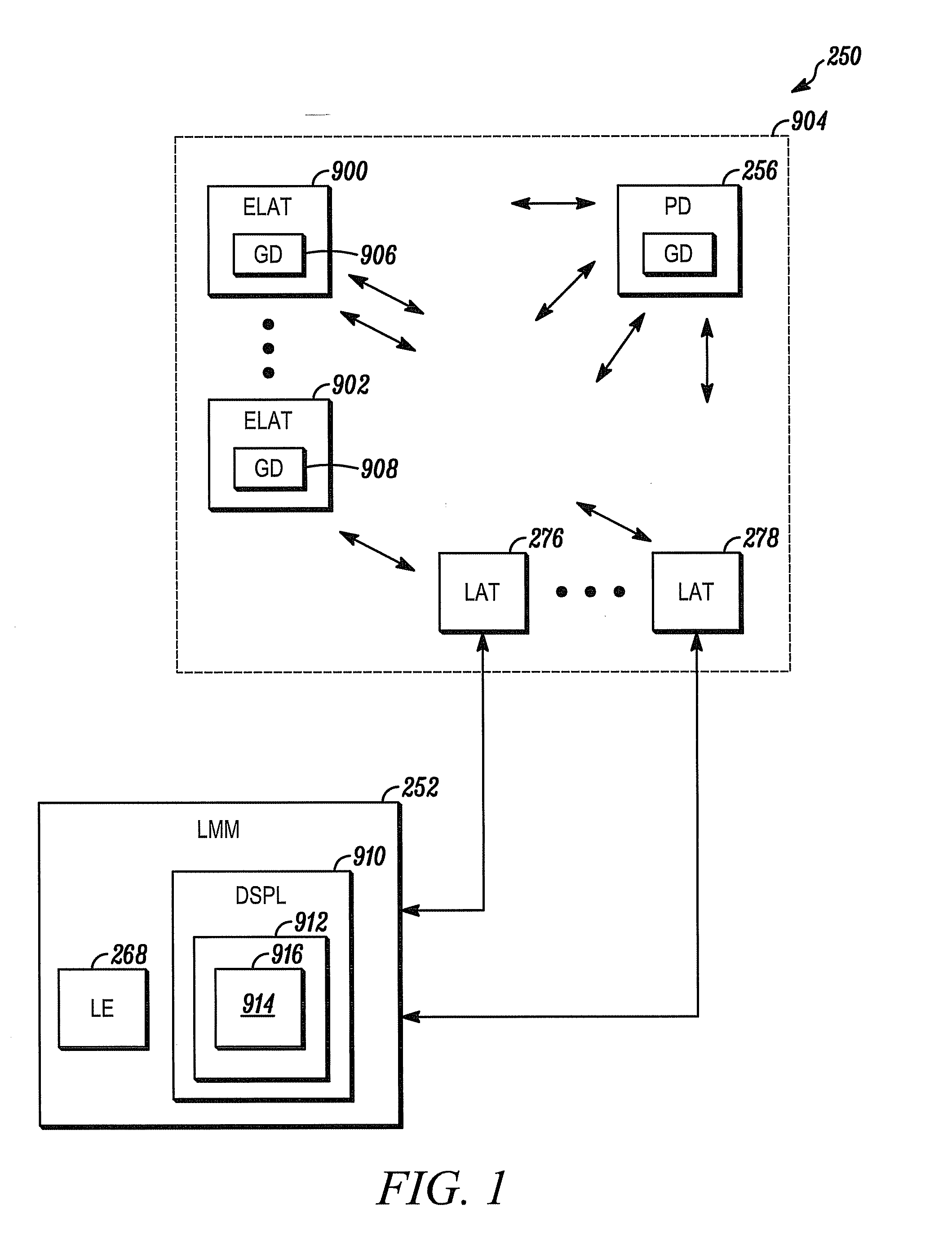
[0008]FIG. 1 depicts a gas detection system 250 shown generally in accordance with an illustrated embodiment of the invention. Included within the gas detection system 250 may be a number of portable gas detectors (transceivers) 256. Also included within the gas detection system 250 is a number of location anchor transceivers 276, 278 connected to a location manager module 252.

[0009]It may be noted that not all location anchor transceivers 276, 278 may be connected to the location manager module 252. Some of the location anchor transceivers 276, 278 may be used only to provide probe responses for location purposes but are not used to relay information to the location manager module 252.

[0010]The location anchor transceivers 276, 278 that are connected to the location manager module 252 may wirelessly receive gas readings and location information from the portable gas detectors 256. The location anchor transceivers may forward this information to the location manager. The location ma...


PUM


Abstract

A method and apparatus are provided for estimating the location of a portable device. The method includes the steps of providing a plurality of location anchor transceivers and a plurality of enhanced location anchor transceivers within a region, each of the plurality of location anchor transceivers and enhanced location anchor transceivers operating from respective predetermined locations, a portable transceiver within the region detecting and measuring a signal parameter of a signal from at least some of the plurality of location anchor transceivers and enhanced location anchor transceivers within the region, a location engine determining a location of the portable transceiver based upon the signal measurements of the portable transceiver and the respective predetermined locations of the plurality of location anchor transceivers and enhanced location anchor transceivers within the region, each of the plurality of enhanced location anchor transceivers detecting and measuring a signal parameter of a signal from at least some of the plurality of location anchor transceivers and other enhanced location anchor transceivers, the location engine receiving the measured signal parameters from each of the plurality of enhanced location anchor transceivers, the location engine calculating an estimated location for each of the plurality of enhanced location anchor transceivers from the measured signal parameters and the location engine calculating a location error for each of the plurality of enhanced location anchor transceivers based upon the estimated location and predetermined location of the enhanced location anchor transceiver.

Description

CROSS-REFERENCE TO RELATED APPLICATIONS[0001]This application is related to and claims priority from U.S. Provisional Patent Application No. 61 / 290,262 filed on Dec. 28, 2009, entitled “Wireless Location-Based System and Method for Detecting Hazardous and Non-Hazardous Conditions” and to U.S. Non-provisional patent application Ser. No. 12 / 695,736, filed on Jan. 28, 2010 and entitled “Wireless Location-Based System and Method for Detecting Hazardous and Non-Hazardous Conditions”, which claims priority from U.S. Provisional Patent Application No. 61 / 290,262, the contents of which are both incorporated herein by reference in their entirety.FIELD OF THE INVENTION[0002]The field of the invention relates to sensing devices and more particularly to portable gas detectors.BACKGROUND OF THE INVENTION[0003]In many environments, it is desirable to detect accumulations of potentially hazardous gases before a hazardous situation exists. An industrial plant, for example, may deploy a gas detectio...

Claims


Application Information

Patent Timeline
IPC IPC(8): G06F15/00
CPCG08B21/14G01S5/0289G06F15/00H04W8/00
Inventor GONIA, PATRICK S.KOLAVENNU, SOUMITRICABUZ, CLEOPATRA
Owner HONEYWELL INT INC
Learn More