Wiper blade and vehicle wiper device

a technology of wiper blade and wiper blade, which is applied in the direction of vehicle maintenance, vehicle cleaning, domestic applications, etc., can solve the problems of negative pressure on the back-face side and in some cases, the wiping characteristic of the wiper blade has deteriorated, so as to facilitate the flow of travel wind, enhance the wiping characteristic of the wiper blade during the travel of the vehicle, and reduce the effect of eddy

Active Publication Date: 2011-07-07
MITSUBA CORP
View PDF4 Cites 16 Cited by
  • Summary
  • Abstract
  • Description
  • Claims
  • Application Information

AI Technical Summary

Benefits of technology

[0008]An object of the present invention is to suppress a water-conducting phenomenon after an inversed operation to enhance a wiping characteristic of a wiper blade during a travel of a vehicle.
[0016]According to the present invention, a flow of travel wind is facilitated between the blade rubber and the rubber holder, and this travel wind can reduce an eddy generated by the travel wind flowing on an upper side of the rubber holder. Therefore, occurrence of a water-conducting phenomenon generated by a negative pressure of the eddy after an inversed operation is suppressed, and a wiping characteristic of the wiper blade during the travel of the vehicle can be enhanced.
[0017]Also, according to the present invention, in the wiper blade in which the covers are coupled to the both longitudinal-direction end portions of the rubber holder, the flow of the travel wind can be facilitated also between the blade rubber and the cover in addition to between the blade rubber and the rubber holder. Therefore, occurrence of a negative pressure due to the eddy over the entire longitudinal-directional range of the wiper blade is reduced, and the wiping characteristic of the wiper blade can be enhanced.
[0018]According to the present invention, since the through hole is formed in the ceiling wall portion of the cover member, and a part of the travel wind is aggressively guided onto a back-face side (vehicle-back side) of the wiper blade via the opening portion, the travel wind guided onto the back-face side of the wiper blade suppresses occurrence of the back-face-side negative pressure due to the travel wind flowing above along the fin. Accordingly, for example, at an upper inversion of the wiper blade, rainwater removed from outside a wiping area can be prevented from being drawn (water-conducting) inside the wiping area by the back-face-side negative pressure. Also, the travel wind entering and flowing in the cover member flows onto a back-face side of the wiper blade and, simultaneously, flows inside the cover member longitudinally along the inner face of the back wall portion. Therefore, the travel wind can be caused to flow out from the back-face side of the wiper blade uniformly over the longitudinal-directional entirety of the wiper blade, and the occurrence of the back-face-side negative pressure over the longitudinal-directional entirety of the wiper blade can be certainly prevented.

Problems solved by technology

However, in the wiper blade shown in Japanese Patent Application Laid Open Publication No. 2006-232078, the travel wind, which flows on an upper side of the wiper blade along the cover member, generates an eddy or eddies on a back-face side of the wiper blade, and a negative pressure is caused on the back-face side of the wiper blade by the eddy.
Therefore, the wiper blade, which inversely operates at an upper inversion position, causes a water-conducting phenomenon in which rainwater etc. swept from outside a wiping range is drawn again into the wiping range by the negative pressure, and its wiping characteristic has deteriorated in some cases.

Method used


Image

  • Wiper blade and vehicle wiper device
  • Wiper blade and vehicle wiper device
  • Wiper blade and vehicle wiper device

Examples


Embodiment Construction

[0034]Hereinafter, embodiments of the present invention will be described in detail based on the accompanying drawings.

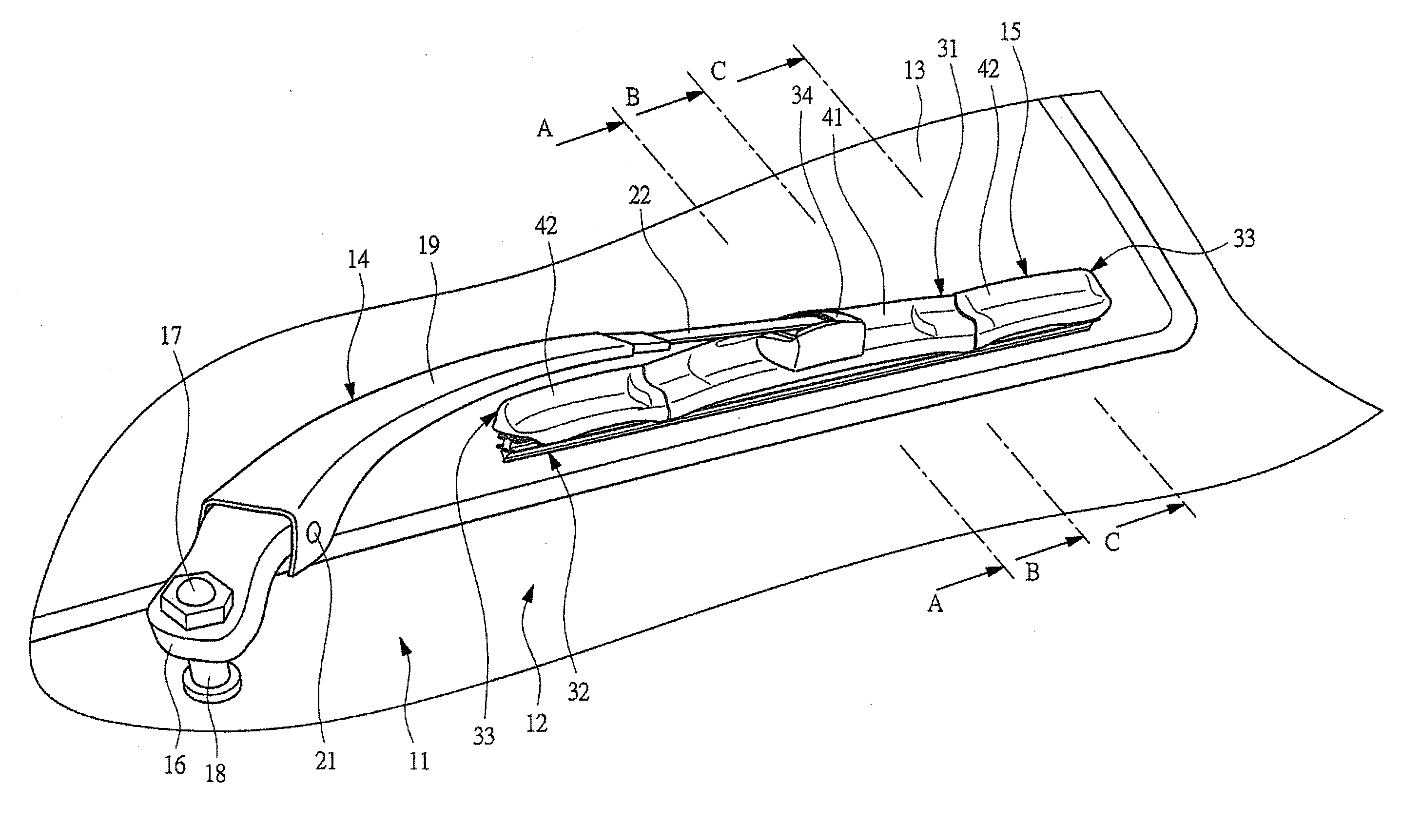
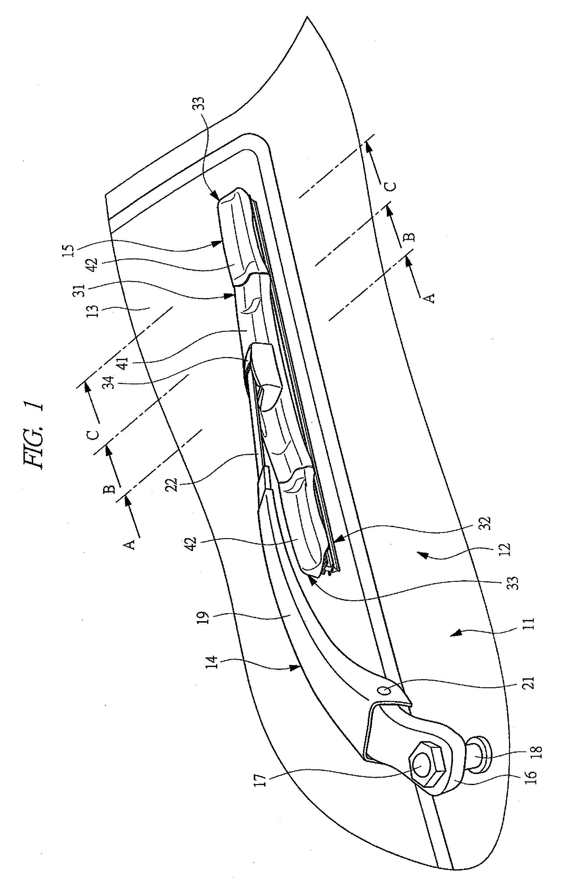
[0035]FIG. 1 is a perspective view showing a vehicle wiper device having a wiper blade according to an embodiment of the present invention, and this vehicle wiper device 11 (hereinafter, abbreviated as “wiper device 11”) is provided to a vehicle 12 such as an automobile to wipe a window glass (windshield glass) 13, and includes a wiper arm 14 and a wiper blade 15 attached to a tip of the wiper arm 14.

[0036]The wiper arm 14 has an arm head 16 made of aluminum die casting, and a base end of the arm head 16 is fixed to a pivot shaft (wiper shaft) 18 swingably provided to the vehicle 12 by a nut 17. The pivot shaft 18 is coupled to an unshown wiper motor equipped with the vehicle 12 via a link mechanism (not shown), and is driven by the wiper motor to swing within a predetermined angle range.

[0037]A retainer 19, which is made of steel plate and is formed into an arm sha...


PUM


Abstract

An interval between an inner face 31c1 of a back wall 31c in a rubber holder 31 and a blade rubber 32 is formed so as to become gradually expanded with respect to an interval between an inner face 31b1 of a front wall 31b and the blade rubber 32 as being directed toward a center portion from both longitudinal-directional end portions of the rubber holder 31. Also, an interval between an inner face of each back wall in a pair of covers coupled to the both longitudinal-directional end portions of the rubber holder 31 and the blade rubber is formed so as to become gradually expanded with respect to an interval between the inner face of the front wall and the blade rubber as being directed toward the center portion from both longitudinal-directional end portions of the cover. Accordingly, a flow of travel wind during a travel of a vehicle is facilitated between the rubber holder 31 and the blade rubber 32 or between the covers and the blade rubber 32.

Description

CROSS REFERENCE TO RELATED APPLICATIONS[0001]This application is entitled to the benefit of and incorporates by reference essential subject matter disclosed in International Patent Application No. PCT / JP2009 / 065265 filed on Sep. 1, 2009 and Japanese Patent Application Nos. 2008-227385 filed Sep. 4, 2008; 2008-227485 filed Sep. 4, 2008; and 2008-319317 filed Dec. 16, 2008.TECHNICAL FIELD[0002]The present invention relates to a wiper blade, which is attached to a tip of wiper arm to wipe a window glass of a vehicle, and relates to a vehicle wiper device.BACKGROUND ART[0003]A vehicle such as an automobile is provided with a wiper device to wipe attachments such as rainwater adhering to a window glass (windshield glass). This wiper device has a wiper arm swingably supported at the vehicle, and a wiper blade is attached to a tip of the wiper blade.[0004]The wiper blade includes a rubber holder with holding claws at both longitudinal-directional end portions, and a blade rubber engaged wi...

Claims


Application Information

Patent Timeline
Patent Type & Authority Applications(United States)
IPC IPC(8): B60S1/38
CPCB60S1/3808B60S1/381B60S1/3801B60S2001/3836B60S1/3863
Inventor FUJIWARA, MASARUIMOTO, KENICHIOGINO, TSUKASA
Owner MITSUBA CORP
Why Eureka
Try Eureka