Rotational gravity/buoyancy power generator

a technology of rotating gravity and power generator, which is applied in the direction of engines, mechanical equipment, machines/engines, etc., can solve the problems of model may actually produce some amount of energy, diamond is flawed, and the gallon of water displaces one gallon of water, so as to increase the potential use and application of the model, reduce the cost of manufacturing and maintenance, and avoid pollution.

Inactive Publication Date: 2011-07-07
HASTINGS DOUGLAS REYNOLDS
View PDF4 Cites 24 Cited by
  • Summary
  • Abstract
  • Description
  • Claims
  • Application Information

AI Technical Summary

Benefits of technology

[0019]It is an object of the rotational gravity / buoyancy power generator to provide an efficient, environmentally friendly power generator.
[0020]It is another object of the rotational gravity / buoyancy power generator to provide an apparatus to generate power without consuming non-renewable resources and which does not generate pollution.
[0021]It is another object of the rotational gravity / buoyancy power generator to provide an apparatus of this character which can be located in almost any location on earth and operate at any time of day or night for generating power and thereby greatly increasing its potential use and application.
[0022]It is a further object of the rotational gravity / buoyancy power generator to provide an apparatus of this character that is relatively inexpensive to manufacture and maintain.
[0023]The characteristics and advantages of the rotational gravity / buoyancy power generator as well as methods, systems and devices for effective utilization and effectiveness thereon, are further sufficiently referred to in the detailed description of the accompanying drawings, which represent several embodiments and are incorporated herein by reference.
[0024]After considering this example, persons skilled in the art will understand that many variations may be made without departing from the principles disclosed and I contemplate the employment of any such structure, arrangements or modes of operation that are properly within the scope of the appended claims.

Problems solved by technology

The problem here is that one gallon of water displaces one gallon of water.
Once again, Diamond is flawed in that it purports to “vary weights of the cylinders from less than the weight of the displaced fluid to more than the weight of the displaced fluid whereby the cylinders may selectively rise and fall within the fluid medium”.
This model may actually produce some amount of energy.
However, Johnson only seeks to capture energy produced by the buoyant force and does not utilize more than 50% of its cycle when merely routing the collapsible buckets through the descent to make them available for inflation and utilization during their ascent.
In Everett and Johnson above, the models are less than 50% efficient since they purposely harvest energy only in the ascent phase of their operations.
Dentler and similar configurations are inferior in that these models utilize varying methods to reintroduce chain-linked, buoyant bodies into the lower portion of a liquid filled tank.

Method used


Image

  • Rotational gravity/buoyancy power generator
  • Rotational gravity/buoyancy power generator
  • Rotational gravity/buoyancy power generator

Examples


Embodiment Construction

[0037]The rotational gravity / buoyancy power generator apparatus is presented in two embodiments though these should not be construed as limitations on the scope of the invention but, rather, the exemplification of several preferred embodiments thereof.

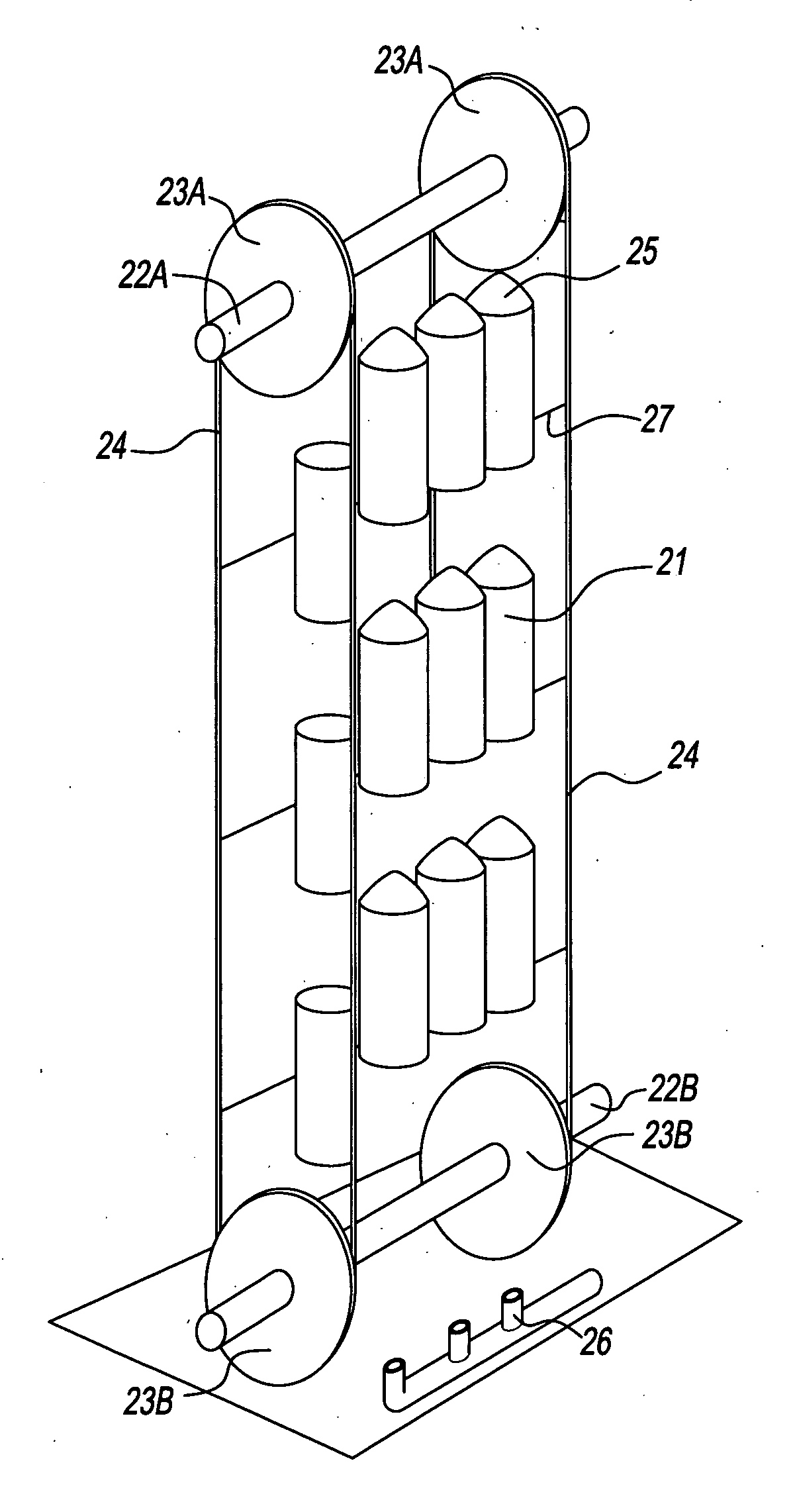
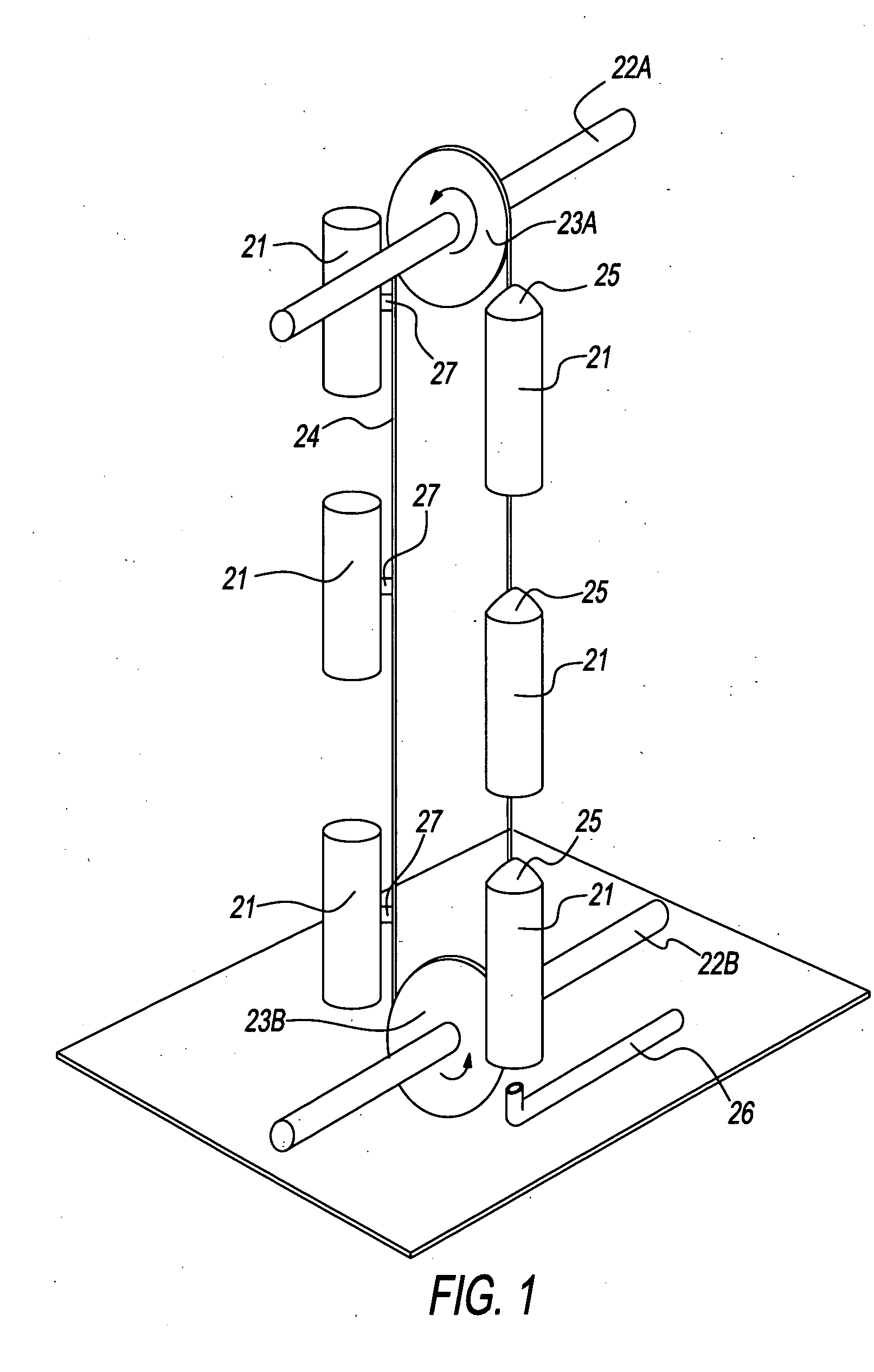
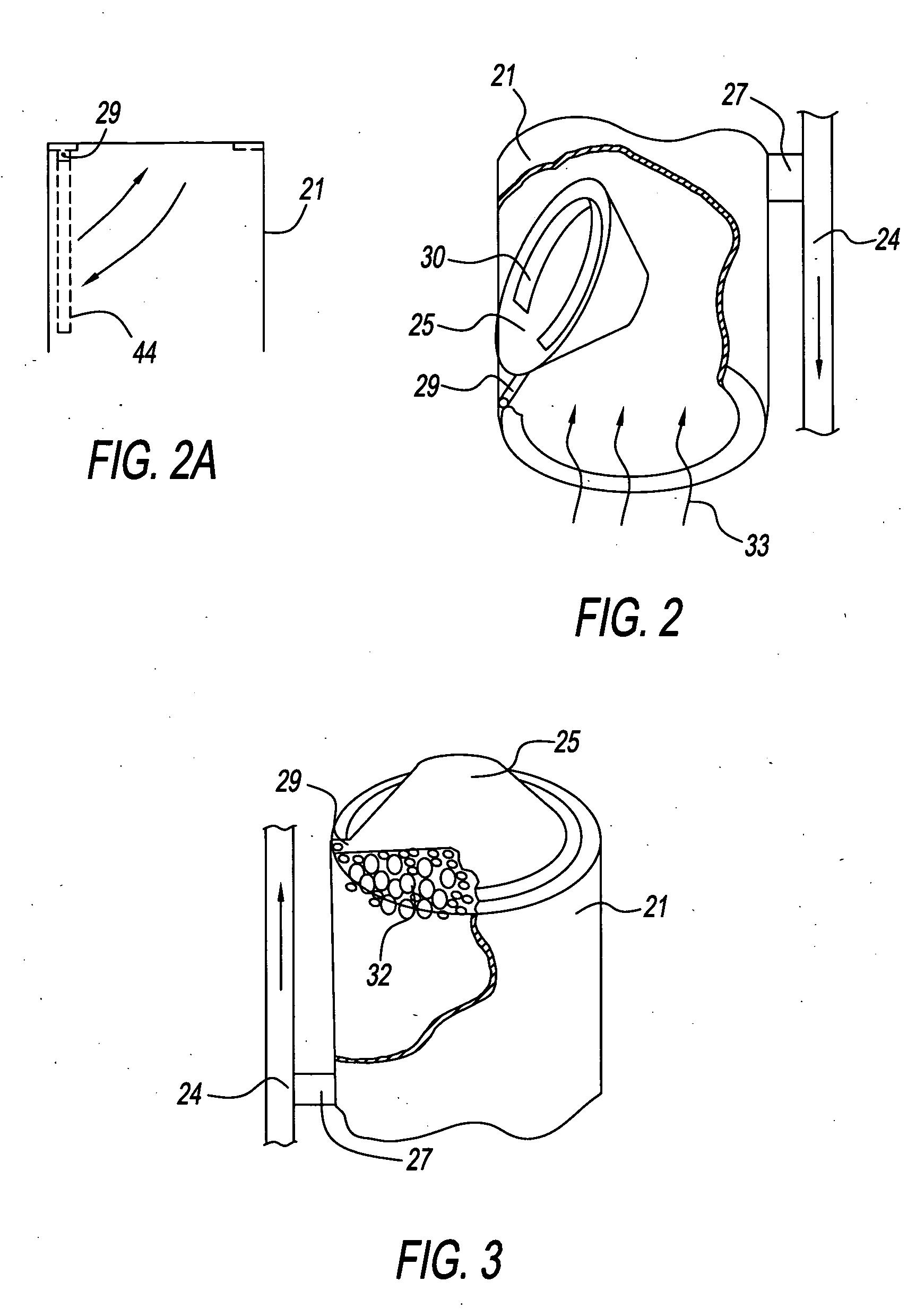
[0038]FIG. 1A shows the most basic, preferred, embodiment for the rotational gravity / buoyancy power generator. In operation the containers (21)—as they ascend and descend through the liquid medium—are attached by brackets (27) to and drive the chain or belt (24) which rotates sprockets or pulleys (23A and 23B). As the container rounds the lower sprocket or pulley (23B) the movable closure means (44) or highly buoyant flapper valve (25) seals what becomes the upper end of the container (FIG. 3). Said closure means or highly buoyant flapper valve may be fitted on its underside with a gas catchment device (26) such that the gas discharge collects primarily in said catchment device to further aid in the air tight sealing capacity of the cl...


PUM


Abstract

The rotational gravity/buoyancy power generator relates to the generation of power by harnessing the gravitational and buoyant forces which act on an apparatus in a natural or man-made liquid medium and converting such forces into mechanical energy. More specifically, the rotational gravity/buoyancy power generator improves on operably different, fluid medium power generators by efficiently utilizing the gravitational force as efficiently as the buoyant force is harnessed. The rotational gravity/buoyancy power generator includes methods, systems and devices for a plurality of weighted containers with a movable closure means on one or both ends, attached to one or more chains, belts or conveyances with one or more rotating sprockets or pulleys on horizontally aligned shafts which form a continuous loop in primarily a vertical arrangement comprising ascending and descending phases upon such apparatus in a continuous and flowing movement (FIG. 1). In the descent phase the containers are open on both ends (FIG. 2) and have greater density than the volume of liquid they displace causing them to rapidly sink through the liquid medium due to the force of gravity. In the ascent phase the containers have either their upper ends sealed, both ends sealed or are filled by internal bladders when, in any embodiment, a volume of gas is introduced such that the overall volume of the containers have a lesser density than the liquid displaced causing the containers to rise through the liquid medium due to the buoyant force. The chains, belts or conveyances to which the containers are attached rotate the sprockets or pulleys and their associated shafts creating mechanical power. Such power can be used to turn electrical generators or other mechanical machines which necessitate such power input.

Description

CROSS REFERENCE TO RELATED APPLICATIONS[0001]This application claims the benefit of Provisional Patent Application Ser. No. 61 / 269,747, filed Jun. 29, 2009 by the present inventorFEDERALLY SPONSORED RESEARCH[0002]noneSEQUENCE LISTING[0003]none[0004]Primary Class: 60 / 495; 60 / 496; 415 / 5renewable and do not deplete resources or pollute the environment. Further, in the United States and many net oil importing countries, there is a need to develop and harness local energy resources to reduce dependence on foreign sources of energy, namely oil.[0005]As a consequence, alternative energy exploration and development proceeds apace to harness energy produced by wind, solar, bioenergy, geothermal, and wave / tidal to name the most scrutinized. Providing a reasonable, steady, continuous and sufficient energy from these sources mostly focuses on their use for generating electricity. However, there are issues with each of these alternative energy sources not the least of which is scalability, effic...

Claims


Application Information

Patent Timeline
Patent Type & Authority Applications(United States)
IPC IPC(8): F03B17/02
CPCF03B17/02Y02E10/20F03B17/04
Inventor HASTINGS, DOUGLAS REYNOLDS
Owner HASTINGS DOUGLAS REYNOLDS
Why Eureka
Try Eureka